
Full Product Manual


ENGLISH
5
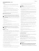
2. Remove the plastic cover, if
present, from the negative
battery terminal and attach
the black cable to the
negative battery terminal (–)
with the bolt (a) and sems
nut (b). See Figure 2.
3. Position the red rubber boot
(c) over the positive battery
terminal to help protect it
from corrosion.
NOTE: If the battery is put into
service after the date shown
on top/side of battery, charge
the battery as instructed in the
Product Care section prior to
operating the mower.
Fuel & Oil
1. The fuel tank has a capacity of five gallons. Remove the fuel cap by turning it counter-
clockwise. Use only clean, fresh (no more than 30 days old), unleaded gasoline. Do
not overfill the fuel tank. Fill the tank to the bottom of the filler neck, allowing some
space in the tank for fuel expansion.
WARNING: Use extreme care when handling gasoline. Gasoline is extremely
flammable and the vapors are explosive. Never fuel the machine indoors or
while the engine is hot or running. Extinguish cigarettes, cigars, pipes, and
other sources of ignition.
2. Your mower is shipped with oil in the engine. However, you MUST check the oil level
before operating. Refer to the Engine Operator’s Manual for oil checking procedures.
WARNING: Always check the engine oil level before each use as instructed
in the Engine Operator’s Manual. Add oil as necessary. Failure to do so may
result in serious damage to your engine.
Tire Pressure
The recommended operating rear tire pressure is 12 psi. The caster wheels are semi-
pneumatic and do not require air pressure. Check the tire pressure periodically and
maintain equal pressure in both rear tires at all times.
IMPORTANT! Refer to the tire sidewall for exact tire manufacturer’s recommended or
maximum psi. Do not overinflate. Uneven tire pressure could cause the cutting deck to
mow unevenly.
USE THE SLOPE GAUGE ON THE BACK COVER AS SHOWN TO DETERMINE IF A SLOPE IS TOO
STEEP FOR SAFE OPERATION!
To check the slope, proceed as follows:
1. Open manual to the back cover and fold along the dashed line.
2. Locate a vertical object on or behind the slope (e.g. a pole, building, fence, tree, etc.).
3. Align either side of the slope gauge with the object.
4. Adjust gauge up or down until the left corner touches the slope.
5. If there is a gap below the gauge, the slope is too steep for safe operation.
SAVE THESE INSTRUCTIONS FOR FUTURE USE
ASSEMBLY & SET-UP
Thank You
Thank you for purchasing this product. It was carefully engineered to provide excellent
performance when properly operated and maintained.
Please read this entire manual prior to operating the equipment. It instructs you
how to safely and easily set up, operate and maintain your machine. Please be sure
that you, and any other persons who will operate the machine, carefully follow the
recommended safety practices at all times. Failure to do so could result in personal injury
or property damage.
All information in this manual is relative to the most recent product information available
at the time. Review this manual frequently to familiarize yourself with the machine, its
features and operation. Please be aware that this Operator’s Manual may cover a range
of product specifications for various models. Characteristics and features discussed and/
or illustrated in this manual may not be applicable to all models. We reserve the right
to change product specifications, designs and equipment without notice and without
incurring obligation.
If applicable, the power testing information used to establish the power rating of
the engine equipped on this machine can be found at www.opei.org or the engine
manufacturer’s web site.
If you have any problems or questions concerning the machine, phone your local
authorized service dealer or contact us directly. We want to ensure your complete
satisfaction at all times.
Throughout this manual, all references to right and left side of the machine are observed
from the operating position.
Contents of Carton
• Mower (1)
• Mower Operator's Manual (1)
• Engine Operator's Manual (1)
Mower Set-Up
Discharge Chute Deflector (If Necessary)
WARNING: Never operate the mower deck
without the chute deflector installed and in the
down position.
1. The chute is shipped attached and with a stop bracket
holding the chute upright. The stop bracket must be
removed prior to operating the tractor. See Figure 1.
2. Holding the chute deflector fully upward, remove the
stop bracket:
a. Grasp the bracket (a) from behind the chute on top of
the deck.
b. Lift up slightly to free the bracket from the notch (b).
c. Pull back to fully remove the bracket.
Connecting the Battery Cables
WARNING: CALIFORNIA PROPOSITION 65: Battery
posts, terminals, and related accessories contain
lead and lead compounds, chemicals known to the State of California to
cause cancer and reproductive harm. Wash hands after handling.
CAUTION: When attaching battery cables, always connect the POSITIVE
(Red) wire to its terminal first, followed by the NEGATIVE (Black) wire.
For shipping reasons, both battery cables on your equipment may have been left
disconnected from the terminals at the factory. To connect the battery cables, proceed
as follows:
NOTE: The positive battery terminal is marked Pos. (+). The negative battery terminal is
marked Neg. (–).
1. Remove the plastic cover, if present, from the positive battery terminal and attach the
red cable to the positive battery terminal (+) with the bolt (a) and sems nut (b). See
Figure 2.
c
b
a
Figure 1
(b)
(b)
(a)
(a)
(c)
Figure 2
CONTROLS & OPERATION
NOTE: References to LEFT, RIGHT, FRONT and REAR indicate that position on the mower
when facing forward in the operator’s position.
NOTE: This Operator’s Manual covers several models. Mower features may vary by
model. Not all features in this manual are applicable to all mower models and the mower
depicted may differ from yours.
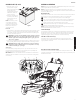
Key Switch (A)
The key switch is located on the console to the rear of the hour meter. The key switch has
three positions on electric start models and two positions on recoil start models.
OFF/STOP — The engine and electrical system are turned off/stopped.
ON — On recoil starter models, the mower electrical system is energized and the
engine can be started using the recoil starter. On electrical starter models, the
mower’s electrical system is energized and the engine is running.
START (electric start models only)— The starter motor will turn over the engine.
Release the key immediately when the engine starts.
NOTE: To prevent accidental starting and/or battery discharge, remove the power key
from the key switch when the mower is not in use.
Choke Knob (B)
The choke knob is located on the control panel below the throttle control lever and to
the left of the PTO knob. The choke is engaged by pulling upward on the choke knob.
Engaging the choke closes the choke plate on the carburetor and aids in starting the
engine. To disengage the choke, push the choke control knob down fully.
Throttle Control Lever (C)
The throttle control is located on the middle of the control panel and is used to
control engine speed. Moving the throttle control upward/forward will increase the
engine speed from slow to fast.
PTO (Power Take-Off) Knob (D)
The PTO knob is located on the center, bottom, of the control panel and is used to
engage the mowing deck. To operate, lift the PTO knob up fully. To stop the blades, push
the PTO knob down fully.
F
A
S
T
S L O W
ASSEMBLY & SET-UP, cont'd
K
FA
ST
SL OW
1
2
3
4
5
6
N
PT
O
R
N
F
STOP
R
N
F
STOP
0.0
I
D
E
G
E
G
F
J
F
C
B
A
L
H
M
Figure 3