TITAN INDUSTRIAL RACK 4-FOOT TALL / 3-SHELF DXST4500 IMPORTANT: Please read this manual carefully before assembling this storage rack and save it for reference INSTRUCTION MANUAL
SAVE THESE INSTRUCTIONS This manual contains important safety and operating instructions. Read all instructions and follow them with use of this product.
TECHNICAL SPECIFICATIONS 4 DXST4500 TECHNICAL SPECIFICATIONS TOTAL CAPACITY 4500 lb (2041 kg) *WHEN WEIGHT IS EVENLY CAPACITY PER SHELF 1500 lb (680 kg) *WHEN WEIGHT IS EVENLY HEIGHT 47” (119.4 cm) WIDTH 49 5/8" (126 cm) DEPTH WEIGHT 18" (45.7 cm) 70.
• Keep work area clean and dry. • Use correct/recommended tools for the job. • Never leave running tools unattended. • Never force a part into place. • Wear safety apparel. • Wear safety glasses/goggles. • Never crawl, sit, stand, or climb on a rack. • Keep small parts away from children. Never leave a small child unattended while assembling. • Always use common sense – your personal safety is your responsibility.
DXST4500 PARTS LIST No. Description Qty. No. Description Qty.
1 2 5 Tools Required for Rack Assembly: 4 mm Hex Key (included) OR 4 mm Hex Bit (included); Rubber Mallet (not included) PARTS LIST 9
DXST4500 EXPANDABLE UPRIGHT FRAME INSTRUCTIONS • Note: For ease of assembly, two (2) Vertical Beams feature pre-bolted horizontal and diagonal beams. 2 ft 18" (61 cm) (45.7 CM) STEP 1 • Place one (1) Vertical Beam and one (1) Pre-Bolted Vertical Beam on the floor, parallel to one another (about 18"/45.7 cm apart). The widest part of the teardrop-shaped hole pattern on each beam should be facing away from you.
CROSSBEAM INSTRUCTIONS Note: It is recommended for one person to hold the upright frames in place while a second person installs the crossbeams. STEP 1 • LOCKING PIN HOLE There is a set of locking tabs at both ends of every crossbeam. To begin assembly, take one crossbeam and insert the tabs into two of the holes on the lower portion of one upright frame. Engage the locking tabs into the holes using a downward motion. The locking pin hole should be at the top.
DXST4500 SHELF SUPPORT AND SAFETY STRAP INSTRUCTIONS • Note: There are three (3) Shelf Support Straps and two (2) Safety Straps with Weld Nuts for every set of crossbeams. STEP 1 • Starting with the lowest set of crossbeams, place one shelf support strap perpendicular to the crossbeams and insert each end into the slots on each side of the crossbeam. STEP 2 ASSEMBLY • Continue aligning the remaining two supports perpendicularly across the beams, and secure them into place.
WALL MOUNTING INSTRUCTIONS • 11 Note: Drywall anchors and anchor screws are included with this rack; however, different wall materials require different types of fasteners. Use fasteners suitable for your specific type of wall. If you are uncertain about what type of fasteners to use, then please contact your local hardware store. STEP 1 • Take the U-shaped bracket and rock it up at an angle to attach it to the bottom inner channel of the crossbeam.
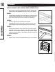
DXST4500 WOOD DECK AND LOCKING SHELF PIN INSTRUCTIONS STEP 1 • Place the first wood deck onto the top ridge of the crossbeams. If seated properly, the deck will “pop” into place and lay evenly. Repeat for the remaining wood decks. STEP 2 ASSEMBLY • There is a locking pin hole at both ends of every crossbeam. This is where the locking shelf pins are to be installed.
STACKING INSTRUCTIONS 13 STEP 3 Line up and place an upright frame on top of one side of the fully assembled rack. Be sure the hole patterns are going in the same direction. The stacking brackets feature a top and bottom set of locking tabs. Engage the top set of tabs into the very bottom of the vertical beam and the bottom set of locking tabs into the very top of the upright frame. Use the same downward motion to attach these brackets as you did for the crossbeams.
DXST4500 REGISTER ONLINE ONE YEAR LIMITED WARRANTY DeWALT will replace this industrial rack due to faulty materials or workmanship for one year from the date of purchase. This warranty does not cover part failure due to normal wear or rack abuse. This warranty does not apply to accessories or damage caused where repairs have been made or attempted. For further detail of warranty coverage, call 1-844-377-8451.