
Full Product Manual
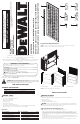
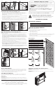
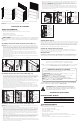
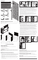

FIG. 1
FIG. 4
FIG. 7
FIG. 10
FIG. 2
FIG. 5
FIG. 8
FIG. 3
FIG. 6
FIG. 9
SIDE
MOUNTING
BRACKET
(RIGHT)
LARGE LOCKING
PIN IN MOUNTING
BRACKETS
HANGING
TAB
PEGBOARD
TOP RACK
UPRIGHTS
LINE UP
AND SLIDE
PEGBOARD
HOLE ONTO
MOUNTING
BRACKET
HANGING
TAB
THEN,
PRESS
PEGBOARD
DOWN
TO
SECURE
IT TO
BRACKET
REAR
MOUNTING
BRACKET
(LEFT)
PEGBOARD
LARGE
LOCKING PIN
LARGE
LOCKING PIN
MOUNTING
TAB ON
PEGBOARD
MOUNTING
BEAM
SMALL
LOCKING PINS
SMALL
LOCKING
PINS
LOCK TAB INTO
MOUNTING BEAM
PEGBOARD
MOUNTING BEAM
1. On each side of the rack place a corresponding back mounting bracket three slots down from
the top, making sure that the hanging tab arrows are pointing upwards. Slide the brackets completely
down into the slots to secure them. Place a second set of brackets spaced one slot below the
previously installed ones, again making sure the arrows point upwards and sliding
them down. (Fig. 4)
2. Slide a pegboard mounting beam vertically onto the mounting tabs of each bracket set. Ensure that the
mounting tabs on the pegboard mounting beam point upwards. (Fig. 4)
3. Line up the slots on the pegboard with the mounting beam’s tabs. Slide the pegboard down completely
onto the tabs to secure it. (Fig. 5)
4. Insert a large locking pin through the largest of the holes in each back mounting bracket to secure them
to the rack uprights. Follow this by inserting two (2) small locking pins into remaining two (2) holes on
each back mounting bracket to secure them to the pegboard mounting beams. (Fig. 6)
NOTE: For the double back configuration, the DXST4500 Industrial Rack (not included) must be adjusted
to work bench configuration.
1. Before assembly can proceed, the DXST 4500 Industrial Rack (not included) must be adjusted to
accommodate for bench top configuration. In general, the top crossbeams should be placed 8 slots
from the top on the rack uprights. The middle crossbeams should be placed 14 slots from the top of
the rack uprights. The lowest crossbeams should be placed 1 slot from the bottom of the rack uprights
or 18 slots from the top of the rack uprights. Make sure the crossbeams are at the same level on
opposing sides and that they are all secured properly before proceeding. The rack shelving can also be
reinstalled at this time. (Fig. 7)
2. Use two (2) sets of back mounting brackets per side on the back of the rack. Insert the first rear
mounting bracket into the first 2 slots from the top of the rack upright followed by the second rear
mounting bracket into the 5th and 6th slots from the top of the rack upright. Then, slide the brackets
down to secure them. Repeat this for both sides. (Fig. 8)
3. Slide a pegboard mounting beam vertically onto the mounting tabs of each bracket set. Ensure that the
mounting tabs on the pegboard mounting beam point upwards. (Fig. 9)
4. Mount the pegboards to the mounting beams starting with the lowest pegboard. Align the pegboard
with the mounting beam tabs and slide it downward until it is fully secured to the tabs. Repeat with the
top pegboard. NOTE: The edges of the pegboards should be relatively flush to the edges of the top
and bottom of the mounting beams. (Fig. 10)
5. Insert a large locking pin through the largest of the holes in each back mounting bracket to secure them
to the rack uprights. Follow this by inserting two (2) small locking pins into remaining two (2) holes on
each back mounting bracket to secure them to the pegboard mounting beams. (Fig. 10)
Single Back Pegboard Panel Assembly (Fig. 4-6)
Double Back Pegboard Panel Assembly (Fig. 7-10)
WORK BENCH
CONFIGURATION
RACK
UPRIGHT
PEGBOARD
MOUNTING
BEAM
LARGE
LOCKING PIN
PEGBOARD
MOUNTING
BRACKET
(LEFT)
SLIDE
BEAM
DOWN AND
LOCK INTO
BRACKET
TABS
SMALL
LOCKING
PINS
START WITH
BOTTOM
PEGBOARD.
SLIDE DOWN
BEAM AND
LOCK INTO
BEAM TABS
One Year Limited Warranty
DEWALT will replace this pegboard due to faulty materials or workmanship for one year from the date of
purchase (please be sure to keep your receipt). This warranty does not cover part failure due to normal
wear or rack abuse. This warranty does not apply to accessories or damage caused where repairs have
been made or attempted. For further detail of warranty coverage, call 1-844-377-8451.
In addition to the warranty, DEWALT pegboards are covered by our:
90 Day Money Back Guarantee
If you are not completely satisfied with the performance of your DEWALT 2 Piece Pegboard Kit for any
reason, you can return it within 90 days from the date of purchase with a receipt for a full refund – no
questions asked.
Latin America
This warranty does not apply to products sold in Latin America. For products sold in Latin America, see
country specific warranty information contained in the packaging, call the local company or see website for
warranty information.
JS PRODUCTS | 6445 MONTESSOURI STREET, LAS VEGAS, NV 89113
CONSERVER CES CONSIGNES
SPÉCIFICATIONS TECHNIQUES
POUR TOUTE QUESTION OU REMARQUE AU SUJET DE CET OUTIL OU DE TOUT AUTRE
OUTIL DEWALT, COMPOSEZ LE NUMÉRO SANS FRAIS: 1-844-377-8451.
Avertissement ! Lire et comprendre toutes les directives.
Ce manuel contient des consignes de sécurité et d’utilisation
importantes. Veuillez lire attentivement ce manuel avant d’assembler
cette étagère de rangement et le conserver à titre de référence.
(APR18) Part No. 41557 DXST4500PBK Copyright © 2018, DEWALT
DEWA LT
®
et le logo DEWALT sont des marques de commerce de DEWALT Industrial Tool Co. ou d’une
société affiliée à cette dernière et sont utilisés sous licence. L’agencement de couleurs jaune et noir est une
marque de commerce des outlils électriques et accessorires DEWALT.
Les définitions ci-dessous décrivent le niveau de danger pour chaque mot indicateur
employé. Lire le mode d’emploi et porter une attention particulière à ces symboles.
indique une situation potentiellement dangereuse qui, si elle n’est
pas évitée, pourrait entraîner la mort ou des blessures graves.
.
indique une situation potentiellement dangereuse qui, si elle n’est pas
évitée, pourrait entraîner des blessures légères ou modérées
(Si utilisé sans aucun terme) Indique un message propre à la sécurité.
indique une pratique ne posant aucun risque de dommages corporels
mais qui par contre, si rien n’est fait pour l’éviter, pourrait poser des risques de
dommages matériels.
AVIS :
Définitions : Règles de sécurité
Spécifications Techniques
Hauteur 18 po (45,72 cm)
Largeur 47 po (119,38 cm)
MESURES DE SÉCURITÉ GÉNÉRALES
• Gardez l’espace de travail propre et sec.
• Utilisez des outils appropriés et recommandés pour le travail à effectuer.
• Ne laissez jamais les outils sans surveillance.
• Ne forcez jamais sur une pièce.
• Portez des vêtements de sécurité.
• Portez des lunettes de protection.
• Assurez-vous de ne jamais ramper sous l’étagère ni de vousy asseoir, de vous y tenir deboutou d’y grimper.
• Gardez les petites pièces hors de la portée des enfants. Ne laissez jamais un jeune enfant sans
surveillance lors de l’assemblage.
• Faites toujours appel à votre bon sens. Vous êtes responsable de votre propre sécurité.
Liste des piéces
N° Description Qté
1 Panneau perforé métallique
2
2 Poutre de montage pour panneau perforé
2
3 Support de montage latéraux (droit)
4
4 Support de montage latéraux (gauche)
4
5 Support de montage arrière (droit)
2
6 Support de montage arrière (gauche)
2
7 Grande goupille de verrouillage 12
8 Petite goupille de verrouillage
8
3 2
1
5
7
4
6
8
REMARQUE : Les panneaux perforés peuvent être montés à l’arrière ou sur les côtés des étagères
pourune organisation multifonctionnelle.
REMARQUE : Regardez les images ci-dessous pour connaître les différentes options de montage des
panneaux perforés.
Orientations d’assemblage des panneaux perforés