
Product Overview


3
PERFORMANCE DATA
www.elcoconstruction.com
©2021 ELCO – REV. A
PERFORMANCE DATA
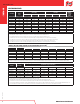
Fastener Strengths
1,2,3,4,5,6,7
Description
Head
Styles
Tension (lbf) Shear (lbf) Minimum
Torsional
Strength
(in-lbs)
Ultimate ASD LRFD Ultimate ASD LRFD
#8-18 HWH 1,580 525 790 1,120 370 560 45
#8-18 PPH 1,375 455 685 1,045 345 520 32
#10-16 HWH 1,845 615 920 1,280 425 640 48
#10-16 PPH, PPCKH, PFH 1,755 585 875 1,405 465 700 43
#12-14 HWH 2,625 875 1,310 1,950 650 975 95
#12-14 PUFH, PPCKH 2,185 725 1,090 1,525 505 760 73
#12-24 HWH 2,730 910 1,365 2,280 760 1,140 95
#12-24 PFH 2,390 795 1,195 1,840 610 920 73
1/4"-14 HWH 3,455 1,150 1,725 2,675 890 1,335 135
1/4"-20 HWH 4,120 1,370 2,060 2,860 950 1,430 135
1/4"-20 PUFH, PFH 3,405 1,135 1,700 2,550 850 1,275 108
1. Ultimate strengths are based on laboratory tests.
2. Allowable (ASD) strengths are based on a safety factor, , of 3.00 in accordance with ICC-ES AC118 and AISI S100-16.
3. Design (LRFD) strengths are based on a resistance factor,
f
, of 0.50 in accordance with ICC-ES AC118 and AISI S100-16.
4. For ASD tension connections, the lower of the ASD tension strength, ASD pull-out strength and ASD pull-over strength must be used for design.
5. For LRFD tension connections, the lower of the LRFD tension strength, LRFD pull-out strength and LRFD pull-over strength must be used for design.
6. For ASD shear connections, the lower of the ASD Shear (Bearing) Capacity and the ASD Fastener Shear Strength must be used for design.
7. For LRFD shear connections, the lower of the LRFD Shear (Bearing) Capacity and the LRFD Fastener Shear Strength must be used for design.
Ultimate Shear (Bearing) Capacity of Screw Connections in Steel, lbf
1,2
Diameter Head Style
Steel Thickness (Lapped Sheets/Bars)
18-18 Ga. 16-16 Ga. 14-14 Ga. 12-12 Ga. 1/8" - 1/8" 3/16" - 3/16"
#8-18 HWH, PPH 805 - - - - -
#10-16 HWH, PPCKH, PFH 865 1,210 1,690 - - -
#12-14 HWH, PPCKH, PUFH 925 1,290 1,805 2,755 - -
#12-24 HWH 925 1,290 1,805 2,755 3,280 4,920
1/4"-14 HWH 995 1,390 1,940 3,190 - -
1/4"-20 HWH 995 1,390 1,940 3,190 3,795 5,695
1. Ultimate strengths are based on calculations in accordance with AISI S100-16.
2. Ultimate load capacities must be reduced by a minimum safety factor to determine allowable loads (ASD) or by a load resistance factor to determine strength design capacities (LRFD).
Allowable (ASD) Shear (Bearing) Capacity of Screw Connections in Steel, lbf
1,2,3,4,5,6
Diameter Head Style
Steel Thickness (Lapped Sheets/Bars)
18-18 Ga. 16-16 Ga. 14-14 Ga. 12-12 Ga. 1/8" - 1/8" 3/16" - 3/16"
#8-18 HWH, PPH 270 - - - - -
#10-16 HWH, PPCKH, PFH 290 405 565 - - -
#12-14 HWH, PPCKH, PUFH 310 430 600 920 - -
#12-24 HWH 310 430 600 920 1,095 1,640
1/4"-14 HWH 330 465 645 1,065 - -
1/4"-20 HWH 330 465 645 1,065 1,265 1,900
1. Allowable (ASD) strengths are based on a safety factor, =3.00, determined in accordance with AISI S100-16.
2. Values are based on steel members with with a minimum tensile strength of Fu = 45 ksi.
3. Allowable (ASD) Shear (Bearing) capacities for other member thicknesses may be determined by interpolating within the table.
4. For ASD shear connections, the lower of the ASD Shear (Bearing) Capacity and the ASD Fastener Shear Strength must be used for design.
5. For steel with a minimum tensile strength F
u
≥ 58 ksi, multiply tabulated values by 1.29 and for steel with a minimum tensile strength F
u
≥ 65 ksi steel, multiply tabulated values by 1.44.
6. The first number is the thickness of steel in contact with the screw head, the second number is the thickness of the steel not in contact with the screw head.
BI-FLEX
®