
Midi-Lathe Instruction Manual

10
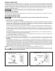
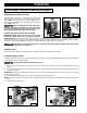
The on/off switch (A) Fig. 15 is located on the bracket (B)
attached earlier to the rear of the headstock. To turn the
switch “ON”, move the switch (A) up to the “ON” position.
To turn the switch “OFF”, move the toggle switch (A) down
to the “OFF” position.
Make sure that the switch is in the “OFF”
position before plugging in the power cord. In the event
of a power failure, move the switch to the “OFF”
position. An accidental start-up can cause injury.
LOCKING THE SWITCH IN THE “OFF” POSITION
IMPORTANT: When the tool is not in use, the switch
should be locked in the “OFF” position to prevent
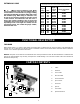
unauthorized use. To lock the machine, grasp the switch toggle (C) Fig. 16 and pull it out of the switch. With the switch
toggle (C) removed, the switch will not operate. However, should the switch toggle be removed while the lathe is running,
the machine can be turned “OFF,” but cannot be restarted without re-inserting the switch toggle (C).
In the event of a power outage (such as a breaker or fuse trip), always move the switch to the “OFF”
position until the main power is restored.
OPERATION
OPERATIONAL CONTROLS AND ADJUSTMENTS
SPINDLE SPEEDS
This wood lathe is capable of providing speeds of 500, 800, 1250, 1800, 2650, and 3700 RPM.
CHANGING SPINDLE SPEEDS
The wood lathe features a six-step motor pulley and spindle pulley to provide the different spindle speeds for particular wood
turning applications. To change speeds:
Disconnect the machine from the power source
!
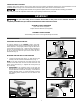
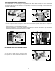
1. Open the doors (A) and (B) Fig. 17 to gain access to the motor pulley (C) Figs. 19 and 20, and spindle pulley (D) Figs. 18
and 20.
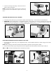
2. Loosen the locking lever (E) Fig. 18. Raise the lever (F) Fig. 18 and tighten the locking lever (E) to enable the drive belt to
move on the pulleys.
IMPORTANT: A speed and belt position chart (G) Figs. 18 and 20 is located on the inside of the door (A) Fig. 17 to help
position the belt correctly.
3. While holding the lever (F) Fig. 18, loosen the locking lever (E). Lower the motor.
NOTE: Push down slightly on the motor with firm finger pressure (to tension the drive belt) before you retighten the locking
lever.
4. Tighten the locking lever (E).
A
B
C
STARTING AND STOPPING THE LATHE
A
B
D
C
G
A
E
F
Fig. 15
Fig. 16
Fig. 17
Fig. 18