
Midi-Lathe Instruction Manual


12
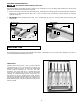
REPLACING THE DRIVE BELT
1 Open the two doors (A) Fig. 26.
2. Hold the handle (B) Fig. 26, and loosen the locking lever (C). Pull up on the handle (B) to remove tension on the drive belt and
then tighten locking lever (C).
3. Loosen the two set screws (D) Figs. 26 and 27, and remove the handwheel (E).
4. Loosen the set screw (G) Fig. 27 on the spindle pulley (H).
Fig. 26
Fig. 27
D
E
D
A
A
B
C
D
E
H
G
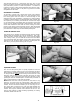
5. Use a soft-tipped mallet (J) Fig. 28 to carefully tap the spindle shaft (K) thru the bearing. Tap it far enough to move the
spindle shaft to the right to remove the spindle pulley (H), and spindle shaft (K), (Fig. 29).
IMPORTANT: Be careful not to drop the metal key (M) Fig. 29 into the hub of the spindle pulley (H).
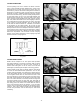
6. Remove the drive belt (A) Fig. 30 from the motor pulley (B).
7. Replace the drive belt and the spindle assembly in reverse order. Apply proper tension to the drive belt. Refer to section
“CHANGING SPINDLE SPEEDS”.
8. IMPORTANT: When attaching the spindle and handwheel, tighten the the set screws in the spindle pulley against the flat
surface of the spindle. Check the spindle pulley to see if it is aligned with the motor pulley. Adjust if necessary.
H
J
K
L
Fig. 28 Fig. 29
Fig. 30
H
M
K
B
A