
Midi-Lathe Instruction Manual

8
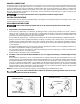
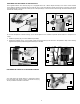
3. Loosen the locking lever (E) Fig.5 and insert the tool
rest (F) in the tool rest base.
NOTE: To adjust the height of the tool rest, loosen the
loching lever (E). After adjustment, tighten the locking
lever.
ATTACHING THE TAILSTOCK TO THE LATHE BED
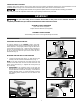
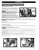
1. The supplied spur center (A) Fig. 8 is equipped with a No. 2 Morse Tapered shank (B). It will fit snugly into the head-
stock spindle.
NOTE: Before inserting, clean both the shank and the headstock spindle to remove grease or debris.
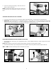
2. Use the knockout bar (C) Fig. 9 through the hole in the opposite end of the spindle to remove the spur center (A).
Be careful of the sharp points on the shank spur center.
Fig. 5
Fig. 7
Fig. 6
Fig. 8
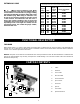
1. Loosen the locking lever (A) Fig. 6, and slide the tailstock assembly (B) Fig. 7 in the channel (C) of the lathe bed.
2. IMPORTANT: If the clamping action on the tailstock (B) Fig. 7 is too tight or too loose on the lathe bed, remove the
tailstock and turn the nut (D) Fig. 7 clockwise to tighten the clamping action, or counter-clockwise to loosen the
clamping action. Attach the tailstock on the lathe bed and tighten locking lever (A) Fig. 6.
ATTACHING THE HEADSTOCK SPUR CENTER TO THE LATHE
F
E
A
B
D
C
A
B
C
A
Fig. 9