ESPAÑOL: PÁGINA 15 FRANÇAISE : PAGE 27 Instruction manual NARROW CROWN STAPLER MODEL NS150A To learn more about Porter-Cable visit our website at: http://www.porter-cable.com IMPORTANT Please make certain that the person who is to use this equipment carefully reads and understands these instructions before starting operations. The Model and Serial No. plate is located on the main housing of the tool. Record these numbers in the spaces below and retain for future reference. Model No.
PORTER✦CABLE Porter-Cable Corporation 4825 Highway 45 North Jackson, TN 38305 GB ENGLISH EC-DECLARATION OF CONFORMITY We declare under our sole responsibility that this product is in conformity with the regulations EN292-2: section 3 of 1992 EN292-1: section 5 of 1992 EN1050: 1993 EN792 13: 2000 E ESPANOL DECLARACION DE CONFORMIDAD ”CE” Declaramos bajo nuestra sola responsabilidad que est e producto está en conformidad con las regulaciones EN292-2: section 3 of 1992 EN292-1: section 5 of 1992 EN1050: 1993
SAFETY GUIDELINES / DEFINITIONS It is important for you to read and understand this manual. The information it contains relates to protecting YOUR SAFETY and PREVENTING PROBLEMS. The symbols below are used to help you recognize this information. indicates an imminently hazardous situation which, if not avoided, will result in death or serious injury. indicates a potentially hazardous situation which, if not avoided, could result in death or serious injury.
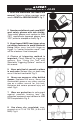
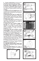
GENERAL SAFETY RULES 1. Read and understand tool labels and manual. Failure to follow warnings could result in DEATH or SERIOUS INJURY. Fig. 1. Fig. 1 2. Operator and others in work area MUST wear safety glasses with side shields. These safety glasses must conform to ANSI Z87.1 requirements (approved glasses have “Z87” printed or stamped on them). Fig. 2. 3. Keep fingers AWAY from trigger when not driving fasteners to avoid accidental firing. Never carry tool with finger on trigger.
9. Do not connect tool to pressure which potentially exceeds 200 PSI (13.7 BAR). 10. All air line components (hoses, connectors, filters, regulators, etc.) must be rated for a maximum working pressure of at least 150 PSI (10.3 BAR) or 150% of the maximum system pressure, which ever is greater. 11. Connect tool to air supply hose with a coupling that automatically removes all pressure from the tool when the coupling is disconnected. Fig. 7. 12.
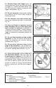
21. Remove finger from trigger when not driving fasteners. Never carry tool with finger on trigger. In “Contact Actuation Mode” tool will fire a fastener if safety is bumped while trigger is depressed. Fig. 14. Fig. 14 22. Do not overreach. Keep proper footing and balance at all times when using or handling the tool. 23. Fire fasteners into work surface only: never into materials too hard to penetrate. Fig. 15. Fig. 15 24.
EMPLOYER’S RESPONSIBILITIES Employer must enforce compliance with the safety warnings and all other instructions contained in this manual. Keep this manual available for use by all people assigned to use this tool. For personal safety and proper operation of this tool, read and understand tool labels and manual. Failure to follow warnings could result in DEATH or SERIOUS INJURY. Read and follow all of these instructions carefully.
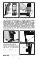
PREPARING THE TOOL 1. After reading and understanding this entire manual, connect tool to air supply (Fig. 18). 2. Pull staple follower all the way to the rear (A) Fig. 19, allowing follower to lock in the open position. Drop a strip of staples onto the guide rail (A Fig. 20). Depress the follower latch button (A) Fig. 21, to unlock the follower and slide forward against staples (A) Fig. 21A. Adjust directional exhaust deflector (A) Fig.
OPERATING INSTRUCTIONS USING THE TOOL WITH SELECTABLE TRIGGERING OPTIONS Complete all steps of PREPARING THE TOOL before using the tool. This tool is shipped from the factory with a selectable trigger set in the “SINGLE SEQUENTIAL ACTUATION” firing mode as described in number 1 below. The selectable trigger can be set for the “CONTACT ACTUATION” firing mode as described in number 2 below; 1. To use the tool in the SINGLE SEQUENTIAL ACTUATION MODE depress trigger lever pivot pin (A) Fig.
Fig. 24 Fig. 23 C D S B A The depth to which a fastener is driven is controlled by the depth adjustment knob (A) Fig. 25. The depth of drive is factory adjusted to a nominal setting. Test fire a fastener and check depth. If a change is desired, rotate the adjustment knob (A) Fig. 25. The adjustment knob has detents every 1/4 turn. Rotate the knob (A) Fig. 25 clockwise to increase the depth of drive, rotate the knob counterclockwise to decrease the depth of drive.
CLEARING A JAMMED FASTENER 1. 2. 3. 4. Disconnect tool from air supply. Hold open spring loaded magazine cover (A) Fig. 28 and remove any remaining fasteners (B) Fig. 29. Remove fasteners from tool before opening the fastener guide plate. Fasteners are under pressure and may shoot out of magazine which could cause injury. Depress the quick release latch (A) Fig. 30 and open the fastener guide plate (B). Remove the jammed fastener (see Fig. 31).
MAINTENANCE CLEAN AND INSPECT DAILY Disconnect tool from air supply before cleaning and inspection. Correct all problems before placing the tool back in use. Wipe tool clean and inspect for wear or damage. Use non-flammable cleaning solutions to wipe exterior of tool only if necessary. DO NOT SOAK tool with cleaning solutions. Such solutions can damage internal parts. Inspect trigger and safety mechanism to assure system is complete and functional: no loose or missing parts, no binding or sticking parts.
TROUBLESHOOTING Disconnect tool from air supply before performing any Service Procedure. SYMPTOM 1. Air leak near top of tool or in trigger area. PROBLEMS Loose screws. Worn or damaged o-rings or seals. SOLUTIONS Tighten screws. Install Overhaul Kit. 2. Tool does nothing or operates sluggishly. Inadequate air supply. Inadequate lubrication. Worn or damaged o-rings or seals. Verify adequate air supply. Put 5 or 6 drops of oil into air inlet. Install Overhaul Kit. 3. Air leak near bottom of tool.
ACCESSORIES A complete line of accessories is available from your Porter-Cable • Delta Supplier, Porter-Cable • Delta Factory Service Centers, and Porter-Cable Authorized Service Stations. Please visit our Web Site www.porter-cable.com for a catalog or for the name of your nearest supplier. Since accessories, other than those offered by PorterCable • Delta, have not been tested with this product, use of such accessories could be hazardous.
PORTER-CABLE • DELTA SERVICE CENTERS (CENTROS DE SERVICIO DE PORTER-CABLE • DELTA) (CENTRE DE SERVICE PORTER-CABLE • DELTA) Parts and Repair Service for Porter-Cable • Delta Power Tools are Available at These Locations (Obtenga Refaccion de Partes o Servicio para su Herramienta en los Siguientes Centros de Porter-Cable • Delta) (Locations où vous trouverez les pièces de rechange nécessaires ainsi qu’un service d’entretien) ARIZONA Tempe 85282 (Phoenix) 2400 West Southern Avenue Suite 105 Phone: (602) 437-12