
Product Overview


TECHNICAL GUIDE – MECHANICAL ANCHORS ©2021 DEWALT – REV. E
A
NCHORS & FASTENERS
REFERENCE DATA (ASD)
Mechanical anchors
10
Wall
Thickness
C2
Min. Edge
Distance
Critical Edge
Distance (see
load tables)
Installation
in this area
for Reduced
Allowable
Load Capacity
No
Installation
Within 1-1/4"
of Head Joint
(unless joint
mortared
full depth)
Anchor
Installation in
this area for
Full Allowable
Load Capacity
Critical End
Distance
(see load
tables)
Min. End
Distance
(end of wall)
A
C1
A
A-A
1. Shear load perpendicular to End and parallel to Edge
2. Shear load perpendicular to Edge and parallel to End
3. Shear load parallel to Edge and perpendicular away
from End
4. Shear load parallel to End and perpendicular to bottom
of wall
Minimum End
Distance (Typ)
Minimum
Edge Distance
(Typ)
Grout Filled
CMU (Typ)
Mortar Joint
1
4
2
3
1. Shear load perpendicular to End and parallel to Edge
2. Shear load perpendicular to Edge and parallel to End
3. Shear load parallel to Edge and perpendicular away from End
4. Shear load parallel to End and perpendicular to bottom of wall
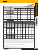
Allowable Screw-Bolt+ Tension and Shear Load Capacities Installed
into the Tops of Grout-Filled Concrete Masonry Units
1,2,3,4,5,6,7,8,9,10
CODE LISTED
ICC-ES ESR-4042
Anchor
Diameter
d
in.
Minimum
Embedment
h
nom
in.
(mm)
Minimum
Spacing Distance
in.
(mm)
Minimum Edge
Distance
in.
(mm)
Minimum End
Distance
in.
(mm)
Tension Load
lbs
(kN)
Shear Load, lb (kN)
Load
Perpendicular to Edge
of Masonry Wall
(II to end)
Load
Parallel to Edge
of Masonry Wall
(
^
to end)
1/4
2-1/2
(63.5)
1-1/2
(38.1)
1-1/2
(38.1)
4
(101.6)
410
(1.8)
185
(0.8)
185
(0.8)
1-1/2
(38.1)
3-1/2
(88.9)
4
(101.6)
485
(2.2)
215
(1.0)
215
(1.0)
3/8
3-1/4
(82.6)
2
(50.8)
1-1/2
(38.1)
4
(101.6)
625
(2.8)
225
(1.0)
505
(2.2)
2
(50.8)
3-1/2
(88.9)
6
(152.4)
625
(2.8)
560
(2.5)
560
(2.5)
1/2
4-1/4
(108.0)
8
(203.2)
(see Note 4 for
reduced minimum
spacing distances)
1-3/4
(44.5)
8
(203.2)
810
(3.6)
255
(1.1)
580
(2.6)
3-3/4
(95.3)
1,210
(5.4)
645
(2.9)
1,030
(4.6)
5/8
5
(127.0)
10
(254.0)
1-3/4
(44.5)
10
(254.0)
900
(4.0)
260
(1.2)
950
(4.2)
3/4
6-1/4
(158.8)
12
(304.8)
1-3/4
(44.5)
12
(304.8)
1,215
(5.4)
260
(1.2)
990
(4.4)
For SI: 1 inch = 25.4 mm; 1 lbs = 0.0044 kN, 1 psi = 0.006894 MPa.
1. All values are for anchors installed in fully grouted concrete masonry wall construction with materials meeting minimum compressive strength, f'm, of 1,500 psi (10.3 MPa). Concrete masonry
units must be light-, medium, or normal-weight conforming to ASTM C90. Allowable loads are based on a safety factor of 5.0.
2. Anchors may be installed in any location in the top of the masonry wall except within 1-1/4-inch from the of the mortar joint (head joint), provided the minimum edge and end distances
are maintained.
3. A maximum of two anchors may be installed in a single masonry cell in accordance with the spacing and edge or end distance requirements. Embedment is measured from the outside surface
of the concrete masonry unit to the embedded end of the anchor. See Screw-Bolt+ Anchors Installed into the Top of Grouted Concrete Masonry Wall figure.
4. Minimum spacing distance for 1/2-inch-diameter anchors shall be 8 inches and may be reduced to 2 inches provided the allowable load reduction factor of 0.40 is applied. Linear interpolation
may be used to determine the reduction factor for intermediate anchor spacing distances between 8 inches and 2 inches.
5. Spacing distance is measured from the centerline to centerline between two anchors.
6. Linear interpolation may be used to for 1/4-inch and 3/8-inch-diameter anchors to determine allowable loads for edge distances between 3-1/2-inches and 1-1/2-inches.
7. Linear interpolation may be used to for 1/2-inch-diameter anchors to determine allowable loads for edge distances between 3-3/4-inches and 1-3/4-inches.
8. The edge and end distance is measured from the anchor centerline to the closest unrestrained edge and end of the CMU block, respectively. See Screw-Bolt+ Anchors Installed into the Top of
Grouted Concrete Masonry Wall figure.
9. Spacing distance is measured from the centerline to centerline between two anchors.
10. Allowable shear loads parallel and perpendicular to the edge of a masonry wall may be applied in or out of plane, respectively. See Screw-Bolt+ Anchors Installed into the Top of Grouted
Concrete Masonry Wall figure.
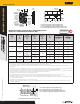
Minimum End
Distance (Typ)
4
1
2
Minimum Edge
Distance (Typ)
3
Grouted Cell (Typ)
1. Shear load perpendicular to End and parallel to Edge
2. Shear load perpendicular to Edge and parallel to End
3. Shear load parallel to Edge and perpendicular away
from End
4. Shear load parallel to End and perpendicular to bottom
of wall
1. Shear load perpendicular to End and parallel to Edge
2. Shear load perpendicular to Edge and parallel to End
3. Shear load parallel to Edge and perpendicular away from End
4. Shear load parallel to End and perpendicular to bottom of wall