
Product Overview


TECHNICAL GUIDE – MECHANICAL ANCHORS ©2021 DEWALT – REV. E
A
NCHORS & FASTENERS
INSTALLATION SPECIFICATIONS (ASD)
Mechanical anchors
2
INSTALLATION SPECIFICATIONS (ASD)
Screw-Bolt+ Anchor Detail Head Marking
d
bit
d
h
h
nom
h
o
d
a
Nomenclature
d
a
= Diameter of Anchor
d
bit
= Diameter of Drill Bit
d
h
= Diameter of Clearance Hole
h = Base Material Thickness.
The value of h should be
1.5h
nom
or 3", whichever is greater
h
nom
= Minimum Nominal Embedment
h
o
= Minimum Hole Depth
Serrated
Underside
Hex Head
Washer
Legend
Diameter and Length
Identification Mark
Legend
Diameter and Length
Identification Mark
Flat Head
(countersunk)
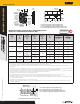
Installation Instructions for Screw-Bolt+ (Hex Head Version Illustrated, Flat Head Version Not Shown)
Step 1
Using the proper
drill bit size, drill a
hole into the base
material to the
required depth.
The tolerances of
the drill bit used
should meet the
requirements of
ANSI standard
B212.15
Step 2
Remove dust
and debris from
hole during
drilling (e.g. dust
extractor, hollow
bit) or following
drilling (e.g.
suction, forced
air) to extract
loose particles
created during
drilling.
Step 3
Select a torque wrench
or powered impact
wrench and do not
exceed the maximum
torque, T
inst,max
or T
impact,max
respectively for the
selected anchor diameter
and embedment. Attach
an appropriate sized
hex socket/driver to the
impact wrench. Mount
the screw anchor head
into the socket.
Step 4
Drive the anchor
into the hole until
the head of the
anchor comes into
contact with the
fixture. The anchor
must be snug
after installation.
Do not spin the
hex socket off
the anchor to
disengage.
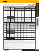
REFERENCE DATA (ASD)
Installation Specifications for Screw-Bolt+ in Concrete and Supplemental Information
Anchor Property/Setting
Information
Notation Units
Nominal Anchor Diameter (inch)
1/4 3/8 1/2 5/8 3/4
Anchor outside diameter d
in.
(mm)
0.250
(6.4)
0.375
(9.5)
0.500
(12.7)
0.625
(15.9)
0.750
(19.1)
Nominal drill bit diameter (ANSI) d
bit
in. 1/4 3/8 1/2 5/8 3/4
Minimum diameter of hole
clearance in fixture
d
h
in.
(mm)
3/8
(9.5)
1/2
(12.7)
5/8
(15.9)
3/4
(19.1)
7/8
(22.2)
Minimum embedment depth
2
h
nom
in.
(mm)
1
(25)
1-1/2
(38)
1-3/4
(44)
2-1/2
(64)
2-1/2
(64)
Minimum hole depth h
o
in.
(mm)
1-3/8
(35)
1-7/8
(48)
2-1/8
(54)
2-7/8
(73)
2-7/8
(73)
Minimum member thickness
1
h
min
in.
(mm)
3
(76)
3
(76)
3
(76)
3-3/4
(95)
3-3/4
(95)
Minimum edge distance c
min
in.
(mm)
1-1/2
(38)
1-1/2
(38)
1-3/4
(44)
1-3/4
(44)
1-3/4
(44)
Minimum spacing s
min
in.
(mm)
1-1/2
(38)
2
(51)
2-3/4
(70)
2-3/4
(70)
3
(76)
Max manual installation torque T
inst,max
ft.-lbf.
(N-m)
19
(26)
25
(34)
45
(61)
60
(81)
70
(95)
Max impact wrench power
(torque)
T
impact,max
ft.-lbf.
(N-m)
150
(203)
300
(407)
300
(407)
700
(950)
700
(950)
Hex Head
Impact wrench socket size - in. 7/16 9/16 3/4 15/16 1-1/8
Maximum head height - in. 21/64 3/8 31/64 37/64 43/64
Maximum washer diameter - in. 37/64 3/4 1-1/16 1-1/8 1-13/32
Flat Head
Driver Size - in. T-30 T-50 T-55 - -
Max head diameter - in. 17/32 57/64 1 - -
Countersunk angle - in. 82 82 82 - -
Effective tensile stress area
(screw anchor body)
A
se
in
2
0.045 0.094 0.176 0.274 0.399
Minimum ultimate strength f
uta
ksi 100 105 115 95 95
Minimum yield strength f
y
ksi 80 84 92 76 76
For SI: 1 inch = 25.4 mm, 1 ft-lbf = 1.356 N-m.
1. The minimum base material thickness shall be the greater of 1.5•h
nom
or 3 inches.
2. See load capacities in normal weight concrete for additional embedment depths.