
Product Overview


TECHNICAL GUIDE – MECHANICAL ANCHORS ©2021 DEWALT – REV. E
A
NCHORS & FASTENERS
REFERENCE DATA (ASD)
9
Mechanical anchors
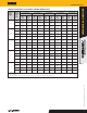
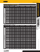
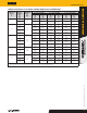
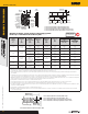
Allowable Screw-Bolt+ Tension and Shear Load Capacities Installed into the
face of Grout-Filled Concrete Masonry Units
1,2,3,4,5,6,7,8,9
CODE LISTED
ICC-ES ESR-4042
Tension Load
Anchor
Diameter, d
in.
Minimum
Embedment
h
nom
in.
(mm)
Allowable Load
at c
cr
and s
cr
lbs
(kN)
Spacing Distance, s
Edge or End Distance, c
2
or c
1
(see Illustration of
Screw-Bolt+ Installed into Grouted Concrete Masonry
Wall detail)
Critical
Distance, s
cr
in.
(mm)
Minimum
Distance, s
min
in.
(mm)
Allowable Load
Factor at s
min
Critical
Distance, c
cr
in.
(mm)
Minimum
Distance, c
min
in.
(mm)
Allowable Load
Factor at c
min
1/4
1-5/8
(41.3)
315
(1.4)
4
(101.6)
2
(50.8)
1.00
(no reduction)
3-3/4
(95.3)
1-1/4
(31.8)
0.60
2-1/2
(63.5)
605
(2.7)
3/8
2
(50.8)
450
(2.0)
6
(152.4)
3
(76.2)
1.00
(no reduction)
6
(152.4)
1-1/2
(38.1)
0.70
3-1/4
(82.6)
1,085
(4.8)
1/2
2-1/2
(63.5)
610
(2.7)
8
(203.2)
4
(101.6)
1.00
(no reduction)
8
(203.2)
2-5/8
(66.7)
0.75
4-1/4
(108.0)
1,190
(5.3)
5/8
3-1/4
(82.6)
880
(3.9)
10
(254.0)
4
(101.6)
1.00
(no reduction)
10
(254.0)
3-3/8
(85.7)
0.90
5
(127.0)
1,270
(5.6)
3/4
4
(101.6)
1,150
(5.1)
12
(304.8)
4
(101.6)
1.00
(no reduction)
12
(304.8)
4
(101.6)
1.00
(no reduction)
6-1/4
(158.8)
1,355
(6.0)
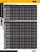
Shear Load
Anchor
Diameter,
d
in.
Minimum
Embedment
h
nom
in.
(mm)
Allowable
Load at c
cr
and s
cr
Direction
1 & 2
lbs
9
(kN)
Allowable
Load at c
cr
and s
cr
Direction
3 & 4
lbs
9
(kN)
Spacing Distance, s
Edge or End Distance, c
2
or c
1
(see Illustration of Screw-Bolt+
Installed into Grouted Concrete Masonry Wall detail)
Critical
Distance, s
cr
in.
(mm)
Minimum
Distance,
s
min
in.
(mm)
Allowable
Load Factor
at s
min
Critical
Distance, c
cr
in.
(mm)
Minimum
Distance,
c
min
in.
(mm)
Allowable Load Factor at c
min
Load
Perpendicular
to Edge
or End
(Direction
1 & 2)
9
Load
Perpendicular
to Edge
or End
(Direction
3 & 4)
9
1/4
1-5/8
(41.3)
400
(1.8)
400
(1.8)
4
(101.6)
2
(50.8)
1.00
(no reduction)
3-3/4
(95.3)
1-1/4
(31.8)
0.35
1.00
(no reduction)
2-1/2
(63.5)
505
(2.2)
505
(2.2)
3/8
2
(50.8)
815
(3.6)
815
(3.6)
6
(152.4)
3
(76.2)
1.00
(no reduction)
6
(152.4)
1-1/2
(38.1)
0.27
1.00
(no reduction)
3-1/4
(82.6)
935
(4.2)
935
(4.2)
1/2
2-1/2
(63.5)
1,380
(6.1)
1,380
(6.1)
8
(203.2)
4
(101.6)
1.00
(no reduction)
8
(203.2)
2-5/8
(66.7)
0.20
1.00
(no reduction)
4-1/4
(108.0)
2,180
(9.7)
2,180
(9.7)
5/8
3-1/4
(82.6)
2,090
(9.3)
2,225
(9.9)
10
(254.0)
4
(101.6)
1.00
(no reduction)
10
(254.0)
3-3/8
(85.7)
0.23
1.00
(no reduction)
5
(127.0)
2,640
(11.7)
2,640
(11.7)
3/4
4
(101.6)
2,800
(12.5)
3,330
(14.8)
12
(304.8)
4
(101.6)
1.00
(no reduction)
12
(304.8)
4
(101.6)
0.25
1.00
(no reduction)
6-1/4
(158.8)
3,100
(13.8)
3,685
(16.4)
For SI: 1 inch = 25.4 mm; 1 lbs = 0.0044 kN, 1 psi = 0.006894 MPa.
1. All values are for anchors installed in fully grouted concrete masonry wall construction with materials meeting minimum compressive strength, f'm, of 1,500 psi (10.3 MPa). Concrete masonry
units must be light-, medium, or normal-weight conforming to ASTM C90. Allowable loads are based on a safety factor of 5.0.
2. Anchors may be installed in any location in the face of the masonry wall (cell, web, bed joint) except within 1-1/4-inch from the of the vertical mortar joint (head joint), center-to-center, provided
the minimum edge and end distances are maintained. Anchors may not be placed in the head joint unless the vertical joint is mortared full-depth.
3. A maximum of two anchors may be installed in a single masonry cell in accordance with the spacing and edge or end distance requirements. Embedment is measured from the outside surface
of the concrete masonry unit to the embedded end of the anchor. See the Illustration of Screw-Bolt+ Anchors Installed into Grouted Concrete Masonry Wall figure.
4. The critical spacing distance, s
cr
, is the anchor spacing where full load values in the table may be used. The minimum spacing distance, s
min
, is the minimum anchor spacing for which values
are available and installation is permitted. Spacing distance is measured from the centerline to centerline between two anchors.
5. The critical edge or end distance, c
cr
, is the distance where full load values in the table may be used. The minimum edge or end distance, c
min
, is the minimum distance for which values are
available and installation is permitted. Edge or end distance is measured from anchor centerline to the closest unrestrained edge.
6. The tabulated values are applicable for anchors installed into the ends of grout-filled concrete masonry units (e.g. wall opening) where minimum edge distances are maintained.
7. Load values for anchors installed less than s
cr
and c
cr
must be multiplied by the appropriate load reduction factor based on actual spacing (s) or edge distance (c). Load factors are multiplicative;
both spacing and edge reduction factors must be considered.
8. Linear interpolation of load values between minimum spacing (s
min
) and critical spacing (s
cr
) and between minimum edge or end distance (c
min
) and critical edge or end distance (c
cr
) is permitted.
9. See the Direction of Shear Loading in Relation to Edge and End of Masonry Wall figure for illustration of shear load directions.