
Product Overview

TECHNICAL GUIDE – MECHANICAL ANCHORS ©2021 DEWALT – REV. E
A
NCHORS & FASTENERS
INSTALLATION SPECIFICATIONS (SD)
13
Mechanical anchors
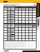
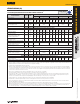
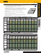
Anchor Setting Information for Installation on the Top of Concrete-
Filled Steel Deck Assemblies with Minimum Topping Thickness
1,2,3,4
CODE LISTED
ICC-ES ESR-3889
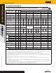
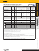
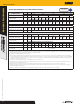
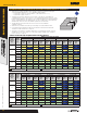
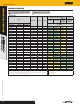
Anchor Property / Setting Information Notation Units
Nominal Anchor Size (inch)
1/4 3/8 1/2
Head style - - Hex Head or Flat Head
Hex Head or
Flat Head
Hex Head or
Flat Head
Nominal anchor diameter d
a
in.
(mm)
0.250
(6.4)
0.375
(9.5)
0.500
(12.7)
Minimum diameter of hole
clearance in fixture
8
d
h
in.
(mm)
3/8
(9.5)
1/2
(12.7)
5/8
(15.9)
Nominal drill bit diameter (ANSI) d
bit
in. 1/4 3/8 1/2
Minimum nominal embedment depth
5
h
nom
in.
(mm)
1-5/8
(41)
2-1/2
(64)
2
(51)
2-1/2
(64)
Effective embedment h
ef
in.
(mm)
1.20
(30)
1.94
(49)
1.33
(33)
1.75
(44)
Minimum hole depth h
o
in.
(mm)
2
(51)
2-1/2
(64)
2-3/8
(60)
2-1/2
(64)
Minimum concrete member thickness
(topping thickness)
h
min,deck
in.
(mm)
2-1/2
(64)
2-1/2
(64)
2-1/2
(64)
2-1/2
(64)
Minimum edge distance c
min,deck,top
in.
(mm)
1-1/2
(38)
2
(51)
2-1/2
(64)
Minimum spacing distance s
min,deck,top
in.
(mm)
1-1/2
(38)
2
(51)
2-1/2
(64)
Minimum nominal anchor length
6
ℓ
anch
in. 1-3/4 2-5/8 2-1/2 3
Maximum impact wrench power
(torque)
T
impact,max
ft.-lb.
(N-m)
150
(203)
300
(407)
300
(407)
Max. manual installation torque T
inst,max
ft.-lb.
(N-m)
18
7
(26)
25
(34)
25
(34)
45
(61)
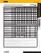
Hex Head
Wrench socket size - in. 7/16 9/16 3/4
Max. head height - in. 21/64 3/8 31/64
Max. washer diameter - in. 37/64 3/4 1-1/16
Flat Head
Driver Size - in. T-30 T-50 T-55
Max head diameter - in. 17/32 57/64 1
Countersunk angle - in. 82 82 82
For SI: 1 inch = 25.4 mm; 1 ksi = 6.894 N/mm
2
; 1 ft-lb = 1.356 N-m; 1 lb = 0.0044 kN.
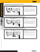
1. The anchors may be installed in the topside of concrete-filled steel deck floor and roof assemblies in accordance with this table, the anchor installation specifications in concrete table and the
top of concrete over steel deck installation detail provided the concrete thickness above the upper flute meets the minimum thicknesses specified in this table. Minimum concrete member
thickness, h
min,deck
, refers to the concrete thickness above the upper flute (topping thickness). See the top of concrete over steel deck installation detail.
2. Applicable to the following conditions:
For 1/4-inch-diameter anchors with 1-5/8-inch nominal embedment, 2-1/2-inch ≤ h
min,deck
< 3-1/4-inch.
For 1/4-inch-diameter anchors with 2-1/2-inch nominal embedment, 2-1/2-inch ≤ h
min,deck
< 4-inch.
For 3/8-inch-diameter anchors with 2-inch nominal embedment, 2-1/2-inch ≤ h
min,deck
< 3-1/2-inch.
For 1/2-inch-diameter anchors with 2-1/2-inch nominal embedment, 2-1/2-inch ≤ h
min,deck
< 4-1/2-inch.
3. For all other anchor diameters and embedment depths, refer to the anchor installation specifications in concrete table for applicable values of h
min
, c
min
and s
min
, which can be substituted for
h
min,deck
, c
min,deck,top
and s
min,deck,top
, respectively.
4. Design capacities shall be based on calculations according to values in Tension Design Information and the Shear Design Information tables.
5. The embedment depth, h
nom
, is measured from the outside surface of the concrete member to the embedded end of the anchor.
6. The listed minimum overall anchor length is based on the anchor sizes commercially available at the time of publication compared with the requirements to achieve the minimum nominal
embedment depth, including consideration of a fixture attachment. The minimum nominal length for hex head anchors is measured from under the head to the tip of the anchor, the minimum
nominal length for flat head anchors is measured from the top of the head to the tip of the anchor.
7. For installations in the topside of concrete-filled steel deck assemblies with normal-weight concrete fill, a maximum installation torque, T
inst,max
, of 19 ft.-lb is allowed.
8. The minimum diameter of fixture hole clearance is for the body of the anchor to pass through structural steel members; clearance holes may be 1/8-inch less than tabulated values (same as
nominal drill bit diameter) provided the screw anchors are installed through light gauge cold-formed steel members or wood members.