© Copyright 2007 Compex Systems Pte Ltd All Rights Reserved This document contains information, which is protected by copyright. Reproduction, adaptation or translation without prior permission is prohibited, except as allowed under the copyright laws. Trademark Information Compex® is a registered trademark of Compex, Inc. Microsoft Windows and the Windows logo are the trademarks of Microsoft Corp. NetWare is the registered trademark of Novell Inc.
FCC NOTICE This device has been tested and found to comply with the limits for a Class B digital device, pursuant to Part 15 of the FCC Rules. These limits are designed to provide reasonable protection against harmful interference in a residential installation. This device generates, uses and can radiate radio frequency energy and, if not installed and used in accordance with the instructions, may cause harmful interference to radio communications.
ICES 003 Statement This Class B digital apparatus complies with Canadian ICES-003. Declaration of Conformity Compex, Inc. declares the following: Product Name: Wireless Access Point with PoE Model No.: WP54AG conforms to the following Product Standards: This device complies with the Electromagnetic Compatibility Directive (89/336/EEC) issued by the Commission of the European Community.
Technical Support Information The warranty information and registration form are found in the Quick Install Guide. For technical support, you may contact Compex or its subsidiaries. For your convenience, you may also seek technical assistance from the local distributor, or from the authorized dealer/reseller that you have purchased this product from. For technical support by email, write to support@compex.com.sg.
About This Document The product described in this document, Wireless Access Point with PoE, WP54AG is a licensed product of Compex Systems Pte Ltd. This document contains instructions for installing, configuring and using Access point. It also gives an overview of the key applications and the networking concepts with respect to the product. This documentation is for both Network Administrators and the end user who possesses some basic knowledge in the networking structure and protocols.
Conventions In this document, special conventions are used to help and present the information clearly. The Wireless Access Point with PoE is often referred to as WP54AG or access point or AP in this document. Below is a list of conventions used throughout.
Copyrights © 2007 Compex Systems Pte Ltd ................................................................ i Trademark Information ..................................................................................................... i Disclaimer ............................................................................................................................ i Your Feedback...................................................................................................................
Setting up your LAN ......................................................................................... 28 To view the active DHCP leases .................................................................... 31 To reserve specific IP addresses for predetermined DHCP clients.......... 32 WLAN Setup ............................................................................................................ 35 To configure the Basic setup of the wireless mode ...................................
To configure Virtual Servers based on IP Forwarding .............................. 129 Bandwidth Control............................................................................................... 130 To enable or disable Bandwidth Control................................................... 130 To configure WAN Bandwidth Control Setting ......................................... 131 To configure LAN Bandwidth Control Setting ........................................... 132 Remote Management ................
APPENDIX I: FIRMWARE RECOVERY .......................................176 APPENDIX II: TCP/IP CONFIGURATION ...................................178 For Windows 95/98/98SE/ME/NT .................................................................. 178 For Windows XP/2000..................................................................................... 181 APPENDIX III: PANEL VIEWS & DESCRIPTIONS ........................184 APPENDIX IV: COMMAND LINE INTERFACE COMMANDS...
Chapter 1: Product Overview INTRODUCTION The Wireless Access Point is a high-performance access point (AP) that is designed for enterprise and public access applications. Embedded with the Atheros chipset, it boasts network robustness, stability and wider network coverage. Based on 802.11g and 802.11a, the access point supports highspeed data transmission of up to 54Mbps in the 2.4GHz and 5GHz frequency band.
FEATURES AND BENEFITS The access point has been designed for high performance and offers a rich suite of features, with which you should acquaint yourself to be able to exploit your access point’s full potential. ! Wireless Distribution System (WDS) This feature allows linking of several access points, virtually creating a larger network infrastructure that allows mobile users to roam wirelessly, while still being able to access network resources.
! HTTPS The access point supports HTTPS (SSL) in addition to the standard HTTP. HTTP (SSL) features additional authentication and encryption for secure communication. ! Telnet Telnet allows a computer to remotely connect to the access point CLI (Command Line Interface) for control and monitoring. ! SSH SSH (Secure Shell Host) establishes a secure host connection to the access point CLI for control and monitoring.
WHEN TO USE WHICH MODE The access point is versatile in the sense that it may operate in six different types of modes: Access Point Mode, Client Mode, Point to Point, Point to Multiple Point, Wireless Routing Client and Gateway. This section presents a brief outline of the different network applications that can be accommodated through the different modes of the access point. ACCESS POINT MODE This is the default mode of your access point.
ACCESS POINT CLIENT MODE In Access Point Client mode, the device acts as a wireless client. When connected to an access point, it will create a network link between the Ethernet network connected at this client device, and the wireless and Ethernet network connected at the access point. In this mode it can only connect with an access point.
POINT TO POINT MODE In Point to Point mode, the access point allows point-to-point communication between different buildings. It enables you to bridge wireless clients that are kilometres apart while unifying the networks.
POINT TO MULTIPLE POINT MODE In Point to Multiple Point mode, this mode is similar to that of the Point-to-Point mode. But the access point located at one facility is able to connect to up to 8 access points (AP) installed in any direction from that facility. The above illustration describes how this mode operates.
WIRELESS ROUTING CLIENT MODE An application of this mode would be for the Ethernet port of the Wireless Routing Client to be used for connection with other devices on the network while access to the Internet would be achieved through wireless communication with wireless ISP. The above illustration describes how this mode operates.
GATEWAY MODE Or put it more simply, Broadband Internet sharing in a wireless network! Since the access point supports several types of broadband connections, the first step in setting up the access point as a Broadband Internet Gateway is to identify the type of broadband Internet access you are subscribed to. Static IP address Use this type of connection if you have subscribed to a fixed IP address or to a range of fixed IP addresses from your Internet Service Provider.
PPP over Ethernet (PPPoE) Select this type of connection if you are using ADSL services in a country utilising standard PPP over Ethernet for authentication. For instance: If you are in Germany which uses T-1 connection or If you are using SingNet Broadband or Pacific Internet Broadband in Singapore. PPTP Select this type of connection if you are using ADSL services in a country utilising PPTP connection and authentication.
WIRELESS ADAPTER MODE Similarly to the Access Point Client mode, the access point used in this mode, is able to communicate wirelessly with another access point to perform transparent bridging between two networks. However here, the Wireless Adapter connects a single wired workstation only. No client software or drivers are required while using this mode.
Chapter 2: Hardware Installation SETUP REQUIREMENTS Before starting, please verify that the following is available: ! CAT5/5e networking cable ! At least one computer is installed with a Web browser and a wired or wireless network interface adapter ! TCP/IP protocol is installed and IP address parameters are properly configured on all your network’s nodes HARDWARE INSTALLATION The access point can be powered using either the power adapter provided or a PoE Injector.
Step 2: Insert one end of the Ethernet cable to any of the Ethernet ports on your access point, and the other end of the cable to your PC’s Ethernet network adapter. PC Step 3: Attach the power adapter to the main electrical supply, and connect the power plug into the socket of the access point. Step 4: Turn ON the power supply and power ON your PC. Notice that the LEDs: Power and Port 1 or 2 (depending on which port you have connected the RJ45 Ethernet cable to) have lighted up.
OPTION TWO: USING POE TO SUPPLY POWER TO THE UNIT The access point is fully compatible with a Power-Over-Ethernet (PoE) kit. A PoE accessory supplies operational power to the wireless AP via the Ethernet cable connection. Users who have already purchased a PoE and who wish to use it to supply power to the access point may follow the installation procedures shown below: Step 1: Connect the external antenna to the SMA connector of the access point.
Step 3: Next, connect the RJ45 Ethernet cable attached to the PoE Injector to your PC’s Ethernet network adapter. Once you have finished configuring your access point, you can connect the PoE Injector’s RJ45 Ethernet cable to your network device, such as to a switch or hub. Step 4: Connect the power adapter supplied in the PoE kit to the main electrical supply and the power plug into the socket of the injector.
Step 5: Turn on your power supply. Notice that the Power LED has lighted up. This indicates that the access point is receiving power through the PoE Injector. Notice also that the corresponding port LEDs have lighted up. This indicates that connection between your access point and your PC has been established.
OPTIONAL: MOUNTING ON THE WALL Step 1: Screw the mount onto the unit. Step 2: Align the unit and mount to the wall. Use the mount as a guide, make 2 marks and drill 2 holes into the wall. Step 3: Next, secure the unit and mount to the wall.
Chapter 3: Access to Web-based Interface There are two methods to access to the web-based Interface of your access point: ! Through our Utility – uConfig You can access to the web-based interface directly without the need to assign a different IP address to your PC. ! By entering the IP address of Access point in the address bar of Internet Explorer You need to assign an IP address to your PC, such as 192.168.168.
Step 3: When the utility has been installed, double-click on the uConfig icon. The following screen will appear, click on the Yes button to proceed. Step 4: Select the access point in the products list and click on the Open Web button. To retrieve and display the latest device(s) in the list, click on the Refresh button.
Step 5: Do not exit the uConfig program while accessing to the web-based interface. This will disconnect you from the device. Click on the OK button to proceed. Step 6: At the login page, press the LOGIN! button to enter the configuration page. The default password is “password”.
Step 7: You will then reach the home page of your access point’s web-based interface.
MANUAL ACCESS TO WEB-BASED INTERFACE VIA INTERNET EXPLORER For this method, you need to assign an IP address to your PC so that it belongs to the same subnet as your access point. In this example, we are using Windows XP for illustration. For Windows 98/98SE/2000/NT/ME, kindly refer to Appendix II “TCP/IP Configuration”. Step 1: Go to your desktop, right-click on My Network Places icon and select Properties. Step 2: Go to your network adapter icon, right click and select Properties.
Step 3: Highlight Internet Protocol (TCP/IP) and click on the Properties button. Step 4: Select the radio button for Use the following IP address. Enter the IP Address and Subnet Mask as 192.168.168.x and 255.255.255.0, where x can be any number from 2 to 254, except 1. In this example, we are using 192.168.168.160 as the static IP Address.
Step 5: Click on the OK button to close all windows. Step 6: Next, in order to check if the IP address has been correctly assigned to your PC, go to Start menu, Accessories, select Command Prompt and type the command ipconfig/all. Your PC is now ready to configure your access point. Step 7: Launch your Web browser. Under the Tools tab, select Internet Options.
Step 8: Open the Connections tab and in the LAN Settings section, disable all the option boxes. Click on the OK button to update the changes. Step 9: At the Address bar, enter http://192.168.168.1 and press Enter on your keyboard. Step 10: At the login page, click on the LOGIN! button to enter the configuration pages.
You will then reach the home page of your access point’s Web interface.
Chapter 4: Common Configuration This chapter illustrates the following features, which are available in ALL the operating modes of your access point, unless stated otherwise. ! Management Port ! WLAN Basic Setup ! WLAN Security ! STP Setup ! SNMP ! MAC Filtering ! Antenna Alignment MANAGEMENT PORT SETUP This section shows you how to customize the parameters of your access point to suit the needs of your network. It also explains how to make use of the built-in DHCP server of your access point.
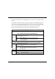
SETTING UP YOUR LAN You can opt to adjust the default values of your access point and customize them to your network settings. Step 1: Click on Management Port from the CONFIGURATION menu. In the Management Port Setup page, refer to the table below to replace the default settings of Access point with appropriate values to suit the needs of your network. Step 2: Click on the Apply button to save your new parameters.
This table describes the parameters that can be modified in the Management Port Setup page. Parameters IP Address Description When the DHCP server of the access point is enabled (unless you set a different DHCP Gateway IP Address), this LAN IP Address would be allocated as the Default Gateway of the DHCP client. The IP address of your Access point is set by default to 192.168.168.1. Network Mask The Network Mask serves to identify the subnet in which your Access point resides.
Parameters DHCP Gateway IP Address Description Though usually, the DHCP server also acts as the Default Gateway of the DHCP client, the access point gives you the option to define a different Gateway IP Address, which will be allocated as the Default Gateway IP of the DHCP client. The DHCP client will thus receive its dynamic IP address from the access point but will access to the Internet or to the other LAN through the Default Gateway defined by the DHCP Gateway IP Address.
TO VIEW THE ACTIVE DHCP LEASES The following will guide you to a page display of the active IP address leases that have been allocated by the built-in DHCP server of Access point. Step 1: Click on Management Port from the CONFIGURATION menu. Step 2: Go to the Advanced DHCP Server Options section, click on the Show Active DHCP leases button.
TO RESERVE SPECIFIC IP ADDRESSES FOR PREDETERMINED DHCP CLIENTS Making an IP address reservation lets you inform the DHCP server to exclude that specific address from the pool of free IP addresses it draws on for dynamic IP address allocation. For instance, if you set up a publicly accessible FTP/HTTP server within your private LAN, while that server would require a fixed IP address, you would still want the DHCP server to dynamically allocate IP addresses to the rest of the PCs on the LAN.
Step 3: Fill in: The host portion of the IP Address to reserve. The Hardware Address, in pairs of two hex values Press the Apply button to make your new entry effective. The DHCP Server Reservations page will then be refreshed to illustrate the currently reserved IP addresses.
DELETE DHCP SERVER RESERVATION If you do not need the DHCP server to reserve an IP address anymore, you can delete the DHCP Server Reservation. Step 1: Click on the reserved IP address that you wish to delete, e.g. 192.168.168.20. Step 2: Click on the Delete button. The DHCP Server Reservations table will then be refreshed to reflect your changes.
WLAN SETUP This section shows how to perform the following functions: Basic: This function performs a basic setup of the wireless modes of operation: Access Point mode, Access Point Client mode and other operating modes. Security: This function performs data encryption and protection for the access point. Kindly refer to Chapter 5 on WLAN Security for details.
TO CONFIGURE THE BASIC SETUP OF THE WIRELESS MODE The following will guide you to configure the basic setup of the wireless mode you have selected. Step 1: Click on WLAN Setup from the CONFIGURATION menu. You will see the submenus expanded under WLAN Setup. Click on Basic. The default operating mode of Access point is the Access Point mode.
Step 2: (Optional: Change Current mode) If you wish to change the current mode of your access point, click on Change, select your Operation Mode and click on the Apply button to access the setup page of your selected mode. Then you are prompted to reboot the access point so as to effect the mode setting.
Step 3: Enter the parameters in their respective fields, click on the Apply button and reboot your device to let your changes take effect. Note that the WLAN Basic Setup page for the Client mode is different from that of the Access Point mode. If you wish to set the access point in the Point-to-Point mode, click on Change to select Point to Point, and then you will see the page below.
If you wish to set the access point in the Point to Multiple Point mode, click on Change to select Point to Multiple Point, and then you will see the page below. To create a new peer MAC, click on the Peer MAC List button. The page will appear. ( Please take note that PtMP stands for Point to Multiple Point ). Click on Add, and then you are prompted to key in Hardware Address and Comment.
This table describes the parameters that can be modified in the WLAN Basic Setup page. Parameters The Current Mode Description The default operating mode of the access point is the Access Point mode. The access point can operate in 6 modes: ! Access Point ! Client ! Point to Point ! Point to Multiple Point ! Wireless Routing Client ! Gateway ! Wireless Adapter You can toggle the mode by clicking on the Change button. ESSID Enter a preferred name for the wireless network.
! 802.11b/g mixed This mode supports both wireless B and G clients. ! 802.11g only This mode supports wireless-G clients that offer transmission rates of up to 54Mbps in the 2.4GHz frequency band. Peer Mac ( Only in Point-to-Point mode ) This mode can support more than one access point. This feature allows you to create a new peer MAC for another access point so that the router operating in the access point mode can connect to another access point.
SCAN FOR SITE SURVEY (ONLY FOR CLIENT MODE AND WIRELESS ROUTING CLIENT MODE ) Step 1: In the Mode Setup page, click on the Site Survey button. The Site Survey provides a list of the MAC addresses (BSSID) and SSID of neighbouring access points detected, the Chan (channels), Auth (Authentication), Alg (Algorithm) used, and the strength of the Signal received.
Step 2: To connect the client to one of the access points detected: Select the radio button corresponding to the access point you want to connect to. Step 3: Click on the Apply button to effect the change and return to the setup page. Step 4: Click on the Refresh button to update this screen. This table describes the read-only parameters of neighbouring access points that can be viewed from the Site Survey page.
NOTE The purpose of using Site Survey is to scan and display all access points based on the current security setting of your access point.
SHOW LINK INFORMATION (ONLY FOR CLIENT MODE AND WIRELESS ROUTING CLIENT MODE) Step 1: To view the connection status when the client is linked to another access point, click on the Show Link Information button.
This table describes the parameters that can be viewed from the Link Information page. Parameters State Description Refers to the MAC address of the BSS (AP to which the client is connected). Current Channel The channel that is being presently used for transmission. Tx Rate Signal Strength The rate of data transmission in Mbps. Given in percentage, showing the intensity of the signal received.
SCAN FOR CHANNEL SURVEY (AVAILABLE FOR ACCESS POINT MODE AND GATEWAY MODE ) Channel Survey provides a list of all channels that are supported by the access point. This feature will show relative interference of all channels and recommend the least congested channel. When the users want to scan for and find the best channel, they can use Channel Survey. Step 1: In the Mode Setup page, click on the Channel Survey button.
The values indicate the level of interference. The higher the value, the higher the interference. If the value is zero, there is no interference. Step 5: To connect the client to one of the channels detected, select the radio button corresponding to the channel you want to connect to. Step 6: Click on the Apply button to effect the change and return to the setup page. Step 7: Click on the Refresh button to update this screen.
This table describes the read-only parameters of all channels that can be viewed from the Channel Survey page. Parameters Freq Description Refers to the frequency of the channel at which your access point is operating. Channel Refers to the channel of the access point being used for transmission depending on its origin of country. MyQuality Indicates the interference level of the respective channel with this AP. The lower the value, the less interference.
ANTENNA ALIGNMENT (AVAILABLE FOR ALL MODES ) The Antenna Alignment feature in the access point is designed to precisely align the antenna over such a long distance so that the connectivity communication between your access point and another remote or neighbouring access point could be improved as indicated by higher signal strength. Step 1: Click on WLAN Setup from the CONFIGURATION menu. You will see the submenus expanded under WLAN Setup. Click on Antenna Alignment.
NOTE If no MAC address is entered, the Antenna Alignment tool will make use of the SSID to align the antenna. Please make sure that the correct SSID is entered. If more than one access point (AP) share the same SSID, the Antenna Alignment tool will show the strongest signal AP.
TO CONFIGURE THE SECURITY SETUP OF THE WIRELESS MODE Kindly refer to Chapter 5 on WLAN Security for details on setting the different security modes of the access point. TO CONFIGURE THE ADVANCED SETUP OF THE WIRELESS MODE The following will guide you to configure the advanced setup of the wireless mode you have selected. Step 1: Click on WLAN Setup from the CONFIGURATION menu to expand into the four sub-menus. From here, click on Advanced. Step 2: In the WLAN Advanced Setup page, enter the parameters.
This table describes the parameters that can be modified in the WLAN Advanced Setup page. Parameters Description Beacon Interval The Beacon Interval is the amount of time between (Only in Access beacon transmissions. A beacon is a guidance signal Point mode) sent by the access point to announce its presence to other devices in the network.
Antenna Control The Antenna Control function allows you to control whether to use the: ! Main antenna ! Aux (auxiliary) antenna ! Auto (Default), to monitor the signal from each antenna and automatically switch to the one with better signal NOTE The values illustrated in the examples are suggested values for their respective parameters. STATISTICS The following shows you the information on the wireless device that is connected to the WLAN.
Step 3: To check the details on individual wireless client, click on the MAC Address in the WLAN Station List. The following screen will show the statistics of the selected wireless client.
IN CLIENT MODE Click on WLAN Setup from the CONFIGURATION menu. You will see the submenus expanded under WLAN Setup. Click on Statistics. In Client mode, you are not allowed to view other wireless clients’ statistics. To view other wireless clients information, you need to change to Access Point mode.
IN POINT TO POINT MODE Click on WLAN Setup from the CONFIGURATION menu. You will see the submenus expanded under WLAN Setup. Click on Statistics.
IN POINT TO MULTIPLE POINT MODE Click on WLAN Setup from the CONFIGURATION menu. You will see the submenus expanded under WLAN Setup. Click on Statistics.
IN WIRELESS ROUTING CLIENT MODE Click on WLAN Setup from the CONFIGURATION menu. You will see the submenus expanded under WLAN Setup. Click on Statistics.
IN GATEWAY MODE Click on WLAN Setup from the CONFIGURATION menu. You will see the submenus expanded under WLAN Setup. Click on Statistics. To view the statistics information if a wireless client connected to the AP, click on the MAC address of that client.
WAN SETUP (only supported by Wireless Routing Client and Gateway) A correct WAN Setup allows you to successfully share your Internet connection among the wired and wireless clients of the access point. To do so, you need to identify the type of broadband Internet access you are subscribed to. If you are using : ! Cable Internet where the ISP dynamically assigns a WAN IP address to you, refer to WAN Setup - Cable Internet with Dynamic IP Assignment.
Step 3: Simply select Dynamic IP Address and hit the Apply button. Please remember to click Reboot System under SYSTEM TOOLS and hit the Reboot button to let the settings take effect. Note: Additional configuration might be required before your ISP will allocate an IP address to the access point. Certain ISPs require authentication through a DHCP Client ID before releasing a public IP address to you. The access point uses the System Name in the System Identity as the DHCP Client ID.
Click on System Identity under the SYSTEM TOOLS command menu. Step 5: On the following screen, key in the your ISP assigned DHCP Client ID as the System Name (You may also like to key in a preferred Systems Contact person and the System Location of the access point). Click the Apply button to complete. Please remember to click Reboot System under SYSTEM TOOLS and hit the Reboot button to let the settings take effect.
WAN Setup - Cable Internet with Static IP Assignment If you have an ISP that leases a static WAN IP for your subscription, you will need to configure your access point’s WAN type accordingly. For example, if the ISP provided you with the following setup information, you can set up your WAN as described below: IP Address : 203.120.12.240 Network Mask : 255.255.255.0 Gateway IP Address : 203.120.12.2 Step 1: Under CONFIGURATION on the command menu, click on WAN Setup.
WAN Setup - ADSL Internet using PPP over Ethernet (PPPoE) If you subscribe to an ADSL service using PPP over Ethernet (PPPoE) authentication, you can set up your access point’s WAN type as follows. For example, you may configure an account whose username is ‘guest’ as described below: Step 1: Under CONFIGURATION on the command menu, click on WAN Setup. Step 2: Access the Select WAN Type page and choose PPP over Ethernet before clicking the Apply button.
You can limit the maximum size a packet can be in a network by setting the MTU (Maximum Transmissible Unit). Click the MTU Button in Advanced WAN Options. The MTU Value has a range of 1 to 1492. Enter the MTU Value and click Apply.
WAN Setup – ADSL Internet using PPTP If you subscribe to an ADSL service using Point-to-Point Tunneling Protocol (PPTP) authentication, you can set up your access point’s WAN type from the steps that follow. For example, if the ISP provided you with the following set up information, you can set up your WAN as described below: IP Address : 203.120.12.47 Network Mask : 255.255.255.0 VPN Server : 203.120.12.15 Step 1: Under CONFIGURATION on the command menu, click on WAN Setup.
WAN Setup – L2TP If you’re using Layer 2 Tunneling Protocol (L2TP) authentication, you can set up your access point’s WAN type from the steps that follow. For example, if the ISP provided you with the following set up information, you can set up your WAN as described below: IP Address : 203.120.12.47 Network Mask : 255.255.255.0 VPN Server : 203.120.12.15 Step 1: Under CONFIGURATION on the command menu, click on WAN Setup.
TELNET/SSH SETUP Telnet allows a computer to remotely connect to the access point CLI (Command Line Interface) for control and monitoring. SSH (Secure Shell Host) establishes a secure host connection to the access point CLI for control and monitoring. Telnet/SSH Setup 1 Click Telnet/SSH Setup from the CONFIGURATION menu. 2 1. 2. To enable Telnet Server: Select Telnet Server Enable and enter the Port Number. To enable SSH server: Select SSH Server Enable and enter the Port Number. Click Apply.
3 To add user: 1. Click Add button. 2. In Add User Entry Page, enter User Name, Password, and specify whether user is granted permission to Read Only or Read/Write. 3. Click Apply. To Delete User: 1. Select which user to Delete. 2. Click Delete.
User Management list refreshes to update users. To Refresh User Management list: Click Refresh to refresh User Management list.
TELNET COMMAND LINE INTERFACE Telnet CLI (Command Line Interface) The user may connect to the CLI (Command Line Interface) via a TELNET session to the default IP, 192.168.168.1. This section uses Microsoft TELNET command for instruction. You may use any TELNET client. Connecting to CLI (Command Line Interface) via TELNET 1. Connect to CLI (Command Line Interface) with the following command at DOS prompt. The TELNET application will then be launched and connect. C:\WINDOWS\TELNET 192.168.168.1 2.
SECURE SHELL HOST COMMAND LINE INTERFACE SSH CLI (Secure Shell Host Command Line Interface) SSH is designed and created to provide the best security when accessing another computer remotely. Not only does it encrypt the session, it also provides better authentication facilities and features that increase the security of other protocols. It can use different forms of encryption and ciphers. The first diagram below shows a telnet session.
SSH CLI has a command line interface like shown below for example.
WEB MODE The access point supports HTTPS (SSL) in addition to the standard HTTP. HTTPS (SSL) features additional authentication and encryption for secure communication. Web Management Setup 1 Select Web Management Setup from the CONFIGURATION menu. 2 1. Select whether to set web server to HTTP or HTTPS (SSL) mode. 2. Click Apply. Changes will be effected after reboot.
SNMP SETUP Simple Network Management Protocol (SNMP) is a set of communication protocols that separates the management architecture from the architecture of the hardware devices. Step 1: Click on SNMP from the CONFIGURATION menu. Step 2: Select Enable from the SNMP State drop-down list. The default Read Password is set to public while the default Read/Write Password is private. Step 3: Click on the Apply button.
STP SETUP (Only available in Access Point, Point to Point and Point to Multiple Point modes) Spanning Tree Protocol (STP) is a link management protocol that helps to prevent undesirable loops occurs in the network. For an Ethernet network to function properly, only one active path can exist between two stations. If a loop exists in the network topology, duplication of messages will occur and this might confuse the forwarding algorithm and allow duplicate frames to be forwarded.
In short, the main purpose of activating STP is to prevent looping when you have redundant paths in the network. Without activating STP, redundant topology will cause broadcast storming. To establish path redundancy, STP creates a tree that spans all of the devices in an extended network, forcing redundant paths into a standby, or blocked, state, but establishing the redundant links as a backup in case the active link should fail.
The path with the smallest cost will be used and extra redundant paths will be disabled. To explain the effect of STP & Pseudo VLAN on the wireless clients, we will compare 3 separate scenarios. Scenario #1 – (No STP, No Pseudo VLAN) Referring to the illustration below, if the Spanning Tree Protocol (STP) and Pseudo VLAN are not implemented in a network, all clients (Notebook#1, #2, #3 & #4,) can access to one another, resulting in low level of data security.
Scenario #2 – (With STP, No Pseudo VLAN) When STP is enabled, extra redundant network paths between APs will be disabled, hence preventing multiple active network paths in-between any two APs. If one of the APs is down, the STP algorithm will reactivate one of the redundant paths so that the network connection will not be lost. All wireless users will be able to communicate with each other if they are associated to the APs that are in the same WDS zone.
Scenario #3 – (With STP and Pseudo VLAN) In this example, both STP and Pseudo VLAN Per Node are implemented in this network. When Pseudo VLAN Per Node is activated, the wireless users will be unable to access one another.
Step 1: Click on STP Setup from the CONFIGURATION menu. Step 2: Select Enable from the STP Status radio button, fill in the fields, and click on the Apply button to update the changes. Priority: (Default: 32768, Range: 0 – 65535) This is the relative priority. The lowest priority will be elected as the root. Hello Time: (Default: 2, Range: 1 – 10) This is the hello time. Every (this number) seconds, a hello packet is sent out by.
MAC FILTERING MAC Filtering acts as a security measure by controlling the users accessing to the network through their MAC address. Each WLAN or radio card supports up to 16 virtual access points and has its own MAC address listing. The client MAC addresses entries can be set apply to all, or to only selected virtual access points. ! NOTE: MAC Filtering will not filter any MAC address from Ethernet port.
Add a MAC address to the MAC Address List. Step 1: Select MAC Filtering from WLAN Setup(a/b/g). MAC Address Filtering page displays. In this page you may also set the MAC Filtering Status to Enable or Disable for access points and set the Policy to either Accept or Deny MAC addresses. MAC Filtering set to Enable with Policy to Accept only the MAC addresses in the MAC Filter Address List and deny all other MAC addresses.
Step 2: MAC Filter Address List page displays. Click the Add button. Step 3: Add MAC Address page displays.
Step 4: Enter the MAC Address of the client in the format xx-xx-xx-xx-xx-xx, where x can take any value in the range 0-9 or a-f. Enter the Comment. This describes the MAC Address you have entered. To apply to all virtual access points: Check Apply to All. To apply to specific virtual access point: Select the checkbox of the corresponding AP. Click the Apply button. Step 5: MAC Filter Address List page displays with updated MAC Address List.
NOTE Please reboot to effect all changes and new MAC address entries. DELETE A MAC ADDRESS FROM ALL ACCESS POINTS. Step 1: Select MAC Filtering from WLAN Setup(a/b/g). MAC Address Filtering page displays. Click View Complete MAC List. (This displays the MAC Address List of the radio card.
Step 2: MAC Filter Address List page displays. Select the checkbox of the MAC address you wish to delete. Click the Delete button. Step 3: MAC Filter Address List page displays with updated MAC Address List.
DELETE A MAC ADDRESS FROM INDIVIDUAL ACCESS POINT. Step 1: Select MAC Filtering from WLAN Setup(a/b/g). MAC Address Filtering page displays. Click Edit for the corresponding access point.
Step 2: MAC Filter Address List page displays. Select the checkbox of the MAC address you wish to delete. Click the Delete button. Step 3: MAC Filter Address List page displays with updated MAC Address List.
EDIT MAC ADDRESS FROM THE MAC ADDRESS LIST. Step 1: Select MAC Filtering from WLAN Setup(a/b/g). MAC Address Filtering page displays. Click Edit. Step 2: MAC Filter Address List page displays. Select the MAC address to edit.
Step 3: The Edit MAC Address page displays. Edit the MAC address settings accordingly. Click Save. Step 4: MAC Filter Address List page displays with updated MAC Address List.
Chapter 5: WLAN Security This section illustrates how to make your WLAN more secure. All the nodes in your network MUST share the same wireless settings to be able to communicate. We will illustrate how to configure each type of security mode individually. To start with, follow the common preliminary steps described below to select the most appropriate security approach for protecting your wireless communications. Step 1: Click on WLAN Setup from the CONFIGURATION menu to select Security.
HOW TO SET UP WEP The guidelines below will help you to set up your access point for using WEP.
Step 1: Specify the key entry type, by selecting either: ! Use Hexadecimal: ! Use ASCII Step 2: Select the Transmission Key from the pull down menu: ! Key 1 ! Key 2 ! Key 3 ! Key 4 The access point lets you define up to four different transmission keys. It defines a set of shared keys for network security. You must enter at least one WEP key to enable security using a shared key.
HOW TO SET UP WPA-PERSONAL (Only available in Access Point mode) The guidelines below will help you to set up the access point for using WPAPersonal. Please follow the steps below if you have activated WPA-Personal, WPA2-Personal or WPA-Personal-AUTO security modes.
Step 3: For WPA-Personal Set the Cipher Type to TKIP. WPA replaces WEP with a strong encryption technology called Temporal Key Integrity Protocol (TKIP) with Message Integrity Check (MIC). For WPA2-Personal Set the Cipher Type to AES. Advanced Encryption Standard (AES) is a stronger symmetric 128-bit block data encryption technique. AES is a requirement of WPA2 under the IEEE 802.11i standard.
HOW TO SET UP 802.1X/RADIUS (Only available in Access Point mode) The guidelines below will help you to set up the access point for using 802.1x/RADIUS. At the IEEE 802.1x Setup page, Step 1: Key in the IP address of the Primary RADIUS Server in your WLAN. You can optionally add in the IP address of a Secondary RADIUS Server, if any. The RADIUS authentication server MUST be in the same subnet as the access point. Step 2: By default, the value for Authentication Port number is 1812.
Step 4: Enter the Shared Secret Key in the field provided. Step 5: By default, the Broadcast Key Rotation is set as 600 seconds. You may leave this value as its default setting. Step 6: Select the length of each encryption key: ! 64- bit 10 hexadecimal or 5 ASCII Text ! 128-bit 26 hexadecimal or 13 ASCII Text Step 7: Press the Apply button and reboot your system, after which your settings will become effective.
HOW TO SET UP WPA ENTERPRISE (Only Access Point mode supports WPA2-Enterprise and WPA-Enterprise-AUTO) The guidelines below will help you to set up the access point for using WPA- Enterprise. Please follow the steps below if you have selected the WPA or WPA1- Enterprise, WPA2- Enterprise or WPA- Enterprise -AUTO. At the WPA1/2-EAP Setup page, Step 1: Key in the IP address of the Primary RADIUS Server in your WLAN. You can optionally add in the IP address of a Secondary RADIUS Server, if any.
Step 3: By default, the value for Accounting Port is 1813. You can leave this value as it is. This value must be set to be the same as the one in the RADIUS server. Step 4: Enter the Shared Secret Key used to validate client-server RADIUS communications. Step 5: Select the length of each encryption key: ! 64- bit 10 hexadecimal or 5 ASCII Text ! 128-bit 26 hexadecimal or 13 ASCII Text Step 6: For WPA-Enterprise Set the Cipher Type to TKIP.
Step 7: Enter the GTK (Group Transient Key) Updates. This is the length of time after which the access point will automatically generate a new shared key to secure multicast/broadcast traffic among all stations that are communicating with it. By default, the value is 600 seconds. Step 8: Press the Apply button and reboot your system, after which your settings will become effective.
Chapter 6: Wireless Extended Features This section illustrates how to configure the wireless extended features. To start with, follow the common preliminary steps described below. ACCESS CONTROL – THE WIRELESS PSEUDO VLAN (Only in Access Point mode) A VLAN is a group of PCs or other network resources that behave as if they were connected to a single network segment although they may be physically located on different segments of a LAN.
WIRELESS PSEUDO VLAN PER NODE When implemented, this mode isolates each wireless client into its own pseudo VLAN. Wireless clients can therefore access resources on the wired network but are unable to see each other or access each other’s data.
The following steps demonstrate how to set up a Wireless Pseudo VLAN per Node. Step 1: From WLAN Setup under Configuration, click on Advanced, which shows the WLAN Advanced Setup page. Step 2: Go to the Extended Features section, and click on the Wireless Pseudo VLAN button. Step 3: The Wireless Pseudo VLAN function is disabled by default. Click on the Change button to make your selection of the type of Pseudo VLAN to implement.
Step 4: Select the Per node radio button and click on the Apply button. The Wireless Pseudo VLAN has configured as Per node.
WIRELESS PSEUDO VLAN PER GROUP The access point can configure up to 32 ‘groups’ of wireless clients identified by their MAC address. Whenever a wireless client requests network access, the access point will first verify whether its MAC address is present in any of the Pseudo VLAN groups. If it is, the access point will grant it access to the wired system resources and to all other wireless clients belonging to the same Pseudo VLAN group only.
The following steps demonstrate how to set up Wireless Pseudo VLAN Groups. CREATE A CLIENT IN A PSEUDO VLAN GROUP Step 1: From the Select Wireless Pseudo VLAN Type page, select Per group and click on the Apply button. Step 2: Click on the Add button to create a client in the Wireless Pseudo VLAN group.
Step 3: Select a group number from the Group drop-down list. Step 4: Fill in the Hardware Address field with the MAC address of the client in the format xx-xx-xx-xx-xx-xx, where x is any value within the range 0-9 or a-f. Step 5: Click on the Add button to update the changes. The Pseudo VLAN group has been added to the list as shown below. NOTE A client can be a member of more than one Pseudo VLAN group.
ADD ANOTHER CLIENT IN A PSEUDO VLAN GROUP Follow the procedures mentioned in Steps 3-5. You can create up to 32 members per Wireless Pseudo VLAN group. EDIT/DELETE A CLIENT IN A PSEUDO VLAN GROUP Step 1: Click on the MAC address in the table as shown below. Step 2: From the Edit Wireless Pseudo VLAN Entry page, Click on the Delete button to remove the client from the group, or Click on the Save button after you had edited the entry.
WIRELESS SETUP - THE WIRELESS DISTRIBUTED SYSTEM (Only in Access Point mode) A wireless distribution system creates a wider network in which mobile users can roam while still staying connected to the available network resources by linking up several access points. In a WDS, the access point can drive a cell of wired and wireless clients while at the same time, connecting to other access points.
Chain Configuration WDS A chain configuration WDS spans an area in length, for instance a long corridor. Satellite access points are chained together starting from a root access point. The access point at either end of the chain will have only one WDS link enabled, while the access points in the middle will have two WDS links configured to associate with the neighboring Access point upward and downward in the chain.
The following steps will guide you in setting up WDS in your access point. CREATE A CLIENT IN A WDS Step 1: From WLAN Setup under Configuration, click on Advanced, which shows the WLAN Advanced Setup page. Step 2: Go to the Extended Features section, and click on the WDS Configuration button.
Step 3: As illustrated on the WDS Setup, the WDS feature is disabled by default. Click on the Change button. Step 4: From the Enable/Disable WDS page, select Enable and click on the Apply button. Step 5: Click on the Add button to create a MAC address of a client.
Step 6: Fill up the Hardware Address field with the wireless MAC address of the device to include in your WDS, using the format xx-xx-xx-xx-xx-xx, where x can take any hexadecimal value 0-9 or a-f. Click on the Add button to update the table. Step 7: From the WDS Configuration page, notice that the MAC Address has been added to the table as shown below.
EDIT/DELETE A CLIENT IN A WDS Step 1: Click on the MAC address in the table as shown below. Step 2: From the Edit WDS Entry page, Click on the Delete button to remove the client from the WDS, or Click on the Save button after you have edited the entry.
LONG DISTANCE PARAMETERS This setup allows the access point to calculate and display suggested values for certain parameters to use to ensure that wireless communication takes place efficiently and effortlessly between physically distant APs. The following steps demonstrate how to configure the Long Distance Parameters. Step 1: From WLAN Setup under Configuration, click on Advanced, which shows the WLAN Advanced Setup page.
Step 3: As illustrated on the Long Distance Parameters Setup page, the Outdoor feature is disabled by default. Select Enable from the pull down menu. Step 4: The access point can automatically calculate the values of the parameters to input based on the distance between your access point and the other wireless device. Enter the distance in meters and click on Show Reference Data.
Step 5: You can enter the parameters according to the recommended values in the pop-up window, click on the Apply button to update the changes. This table describes the parameters that can be modified in the Long Distance Parameters page. Parameters Outdoor Description The Outdoor parameter is disabled by default. If set to Enable, the Outdoor parameters will be configured for outdoor communication over short or long distances as specified.
Chapter 7: Advanced Configuration ROUTING (only supported by Wireless Routing Client and Gateway) The access point allows the network administrator to add a static routing entry into its routing table so that the access point can re-route IP packets to another network access point. This feature is very useful for a network with more than one access point. Important: You do NOT need to set any routing information if you are simply configuring the access point for broadband Internet sharing.
The diagram below illustrates a case in which you have two routers in the network. One router is used for broadband Internet sharing while another router connects to a remote office. You may then define a static routing entry in the access point to re-route the packets to the remote office. Static Routing 56K analog modem POTS 56K analog modem INTERNET Access point 192.168.168.1 Cable/ADSL modem 192.168.168.254 REMOTE OFFICE Workstations Wireless Clients Subnet 192.168.100.
TO CONFIGURE STATIC ROUTING With an understanding of how adding a static routing entry can facilitate a network setup such as the one described above, here is how you may configure the access point: Step 1: Under the CONFIGURATION command menu, click on Routing to be brought to the System Routing Table shown (on the right). Initially, the table will contain the default routing entries built into Access point. Step 2: Click on the Static Routing Table button above. On this page, click the Add button.
NAT (only supported by Wireless Routing Client and Gateway) The basic purpose of NAT is to share a single public IP address when there are multiple PCs in the private network by using different TCP ports to identify requests coming from different PCs. NAT is enabled by default. Due to NAT, computers in the private LAN behind the access point will not be directly accessible from the Internet.
TO CONFIGURE VIRTUAL SERVERS BASED ON DE-MILITARIZED ZONE HOST Having gone through the NAT Technology Primer on the Product CD, you would now have a good understanding of how DMZ works to make a specific PC in an NAT-enabled network directly accessible from the Internet. When NAT is enabled, an Internet request from a client within the private network first goes to the access point receiving a request, the access point keeps track of which client is using which port number.
You may wish to set up a DMZ host if you intend to use a specialpurpose Internet Service such as an online game for which no i NOTE 1. When you enable DMZ, the Static IP Address configuration is recommended for the DMZ host. Otherwise, if the address is allocated by DHCP, it may change and DMZ will not function properly. 2. DMZ allows the host to expose ALL of its parts to the Internet. The DMZ host is thus susceptible to malicious attacks from the Internet.
TO CONFIGURE VIRTUAL SERVERS BASED ON PORT FORWARDING Virtual Server based on Port Forwarding is implemented to forward Internet requests arriving at the access point’s WAN interface, based on their TCP ports, to specific PCs in the private network. If you require more information on this function, please refer to the NAT Technology Primer on the Product CD. Step 1: Under the CONFIGURATION command menu, click on NAT. You will find the Advanced NAT Options available near the bottom of the page.
Step 4: On the following Add Port Forward Entry screen, you can set up a Virtual Server for a Known Server type by selecting from a drop-down menu OR you can define a Custom Server. For a more detailed explanation, please refer to the NAT Technology Primer found on the Product CD.
Known Server : Server Type Select from the drop-down list of known server types: (HTTP, FTP, POP3 or Netmeeting). Private IP : Specify the LAN IP address of your server PC running within the private network. Address Public IP : Select All, Single, or Range from the dropdown list. From : Enter the beginning of the range. To : Enter the end of the range. Server Type : Define a name for the server type you wish to configure.
TO CONFIGURE VIRTUAL SERVERS BASED ON IP FORWARDING When you have subscribed for more than one IP address from your ISP, you may define Virtual Servers based on IP Forwarding for which all Internet requests, regardless of ports, are forwarded to defined computers in the private network. If you require more information of its function, please refer to the NAT Technology Primer on the Product CD. Here are the steps to set it up: Step 1: Under the CONFIGURATION command menu, click on NAT.
BANDWIDTH CONTROL (only supported by Wireless Routing Client and Gateway) The access point is designed to support simple bandwidth management that makes use of the Bandwidth Control. This feature gives the administrator the choice to manage the bandwidth control of subscribers in case of massive data transfer that causes slowdown problems when surfing the Internet. TO ENABLE OR DISABLE BANDWIDTH CONTROL Only two simple steps are required to enable or disable bandwidth control for the access point.
Step 2: By default, Bandwidth Control is disabled. Select Enable, followed by clicking the Apply button. TO CONFIGURE WAN BANDWIDTH CONTROL SETTING The access point can allow you to limit the entire throughput by configuring the Upload / Download Bandwidth Setting option. These values should be set to a positive integer indicating the maximum number of kilobytes transferred per second that will be allowed. The value of zero means unlimited.
TO CONFIGURE LAN BANDWIDTH CONTROL SETTING The access point can allow you to limit the LAN user’s throughput by configuring the Bandwidth Control Rule. Step 1: Under the CONFIGURATION command menu, click on Bandwidth Control to select LAN Bandwidth Control Setup. Step 2: Click Add to create the bandwidth rule for LAN user. Step 3: Click Add to create the rule for LAN user’s bandwidth control.
This table describes the parameters that can be modified in the Add Bandwidth Control Entry page. Parameters Rule Name Committed (kbit) Description The rule describes the type of bandwidth traffic to be controlled and of a specification of what action to take when that bandwidth traffic is encountered. Rate This is the minimum bandwidth rate at which a user can get the throughput. Ceiling Rate (kbit) This is the capped bandwidth rate to limit a user’s throughput.
REMOTE MANAGEMENT (only supported by Wireless Routing Client and Gateway) The advanced network administrator will be delighted to know that remote management is supported on the access point. With this feature enabled, you will be able to access the access point’s web-based configuration pages from anywhere on the Internet and manage your home/office network remotely. TO SET UP REMOTE MANAGEMENT Only two simple steps are required to set up remote management for the access point.
PARALLEL BROADBAND (only supported by Gateway) The access point is equipped with the exclusive Parallel Broadband technology to provide scalable Internet bandwidth with Load Balancing and Fail-Over Redundancy.
TO ENABLE PARALLEL BROADBAND Before you begin, ensure that each of the access point within the network is properly configured to connect to its individual broadband Internet account. Then ensure that either: ! each access point is connected to an Ethernet port in the network as illustrated above or ! the access points are interconnected by WDS or ! the access points are wired to each other.
EMAIL NOTIFICATION The access point provides this feature to notify you by email when there is a change in the WAN IP address that was supplied to you earlier. Step 1: Under the CONFIGURATION command menu, click on WAN PPPoE Setup or WAN PPTP Setup, and you will be brought to the following screen. Step 2: Click on the Email Notification button.
! Email address of Receiver: This is the email address of the receiver to whom the message would be sent. ! IP address of Email Server: This is the IP address of the SMTP server through which the message would be sent out. (Take note that you are encouraged to use your ISP’s SMTP server). ! User Name: This is the mail account user’s name that should be entered if authentication is required. ! Password: This is the mail account user’s password that should be entered if authentication is required.
STATIC ADDRESS TRANSLATION (only supported by Wireless Routing Client and Gateway) If you use a notebook for work at the office, it is probable that you also bring it home to connect to the Internet and retrieve emails or surf the web. Since it is most likely that your office’s and your home’s broadband-sharing network subnets are differently configured, you would have to struggle with reconfiguring your TCP/IP settings each time you use the notebook in a different place.
Step 1: Under the Home User Features command menu, click on Static Address Translation. Step 2: You may then choose to Enable or Disable Static Address Translation here, followed by clicking the Apply button.
DNS REDIRECTION (only supported by Wireless Routing Client and Gateway) When you enter a URL in your Internet browser, the browser requests for a name-to-IP address translation from the Domain Name System (DNS) servers to be able to locate the web server hosting the website you want to access. The DNS server, in turn, looks for the answer in its local cache and if an appropriate entry is found, sends back this cached IP address to the browser.
NOTE For Internet access, please do NOT leave the DNS Server field of the PC’s TCP/IP Properties blank. Simply key in any legal IP address for it (e.g. 10.10.10.10) even though you do not have the exact DNS IP address.
TO ENABLE/DISABLE DNS REDIRECTION Step 1: Under the Home User Features command menu, click on DNS Redirection. Step 2: Simply choose Enable or Disable for the Status of DNS Redirection. Step 3: Complete the setup by clicking the Apply button. DYNAMIC DNS SETUP It is difficult to remember the IP addresses used by computers to communicate on the Internet.
TO ENABLE/DISABLE DYNAMIC DNS SETUP Step 1: Under the Home User Features command menu, click on Dynamic DNS Setup. Step 2: You may then choose to Enable or Disable Dynamic DNS here, followed by clicking the Apply button. (Note: Dynamic DNS is disabled by default) TO MANAGE DYNAMIC DNS LIST Step 1: Under the Home User Features command menu, click on Dynamic DNS Setup. Step 2: If you have already created a list earlier, click on the Refresh button to update the list.
Step 3: To add a new Dynamic DNS to the list, click on the Add button and you will see the Choice DDNS Provider page appear. There are two default providers that you can use. The following parameters are explained below: ! Choice : This allows you to check the radio button of your preferred DDNS provider. ! Provider Name : This is the name of your preferred DDNS provider. ! Register Now : This allows you to go to the website of your preferred DDNS provider where you can register your account.
dynamic WAN IP connection is used. For instance, If your ISP connection service uses the dynamic WAN IP, tick the Auto Detect checkbox to let the DDNS server learn your current WAN IP address. Enter your DDNS account Username and Password. However, if you are using a fixed WAN IP connection, enter the IP address in the WAN IP field. Then, un-tick the Auto Detect checkbox. Then the access point will update the DDNS server using that WAN IP entered in its field.
Step 6: Click on the Add button to save the new addition. Step 7: The new domain is added to the Dynamic DNS list table. Step 8: It will appear as a hyperlink that you can click to go back to the Dynamic DNS Edit page. From this page, you can update any of the parameters, delete the domain name or reset all parameters to be blank again.
To select DtDNS as DDNS Service Provider Step 1: Under the Choice column in the table of Choice DDNS Provider check the radio button next to the DtDNS. Then click on the Next button to proceed. Step 2: Enter your Domain Name. Step 3: The Auto Detect checkbox is ticked by default. The WAN IP entry box is blank by default. These default settings should be applied if the dynamic WAN IP connection is used.
Step 5: In our example, while the new domain name, cool.3d-game.com is being added to the list, the message ‘Waiting in queue…” will be displayed under the Update Status column of the Dynamic DNS List table.
Chapter 8: Security Configuration ! This chapter describes the security configuration mainly found in the Wireless Routing Client and Gateway modes. PACKET FILTERING As part of the comprehensive security package found on the access point, you may perform IP packet filtering to selectively allow/disallow certain applications from connecting to the Internet. TO CONFIGURE PACKET FILTERING Step 1: Under the Security Configuration command menu, click on Packet Filtering.
Step 4: Click on the Add button and you will be able to define the details of your Packet Filter Rule from the screen on the right. 4a). Enter Rule Name for this new packet filtering rule. example, BlockCS For 4b). From the IP Address drop down list, select whether to apply the rule to: ! A Range of IP addresses In this case, you will have to define (From) which IP address (To) which IP address, your range extends.
! A Range of TCP ports In this case, you will have to define (From) which port (To) which port, your rule applies. ! A Single TCP port Here, you need only specify the source port in the (From) field. ! Any IP port You may here, leave both, the (From) as well as the (To) fields, blank. Here, the rule will apply to all ports. 4d).
! Any time Here, you may leave both (From) and (To) fields blank. Step 5: Click on the Apply button to make the new rule effective. The Filtering Configuration table will then be updated. Step 6: In this example, let us say we would like to block an application called CS from all PCs (any IP address within the network) from Monday to Friday 7am to 6pm, and this application is using the port number 27015. Therefore, for a rule we name BlockCS, and add the entries depicted on the left.
URL FILTERING The access point supports URL Filtering, which allows you to easily set up rules to block objectionable web sites from your LAN users. TO CONFIGURE URL FILTERING Step 1: Under the Security Configuration command menu, click on URL Filtering. Step 2: You may now define the URL Filter Type by clicking the Change button. Step 3: Select Block or Allow, and then click on the Apply button. The default is Disabled, which allows all websites to be accessed.
FIREWALL CONFIGURATION More than just a “NAT” firewall, there is a powerful Stateful Packet Inspection (SPI) firewall option that can be activated on the access point. Stateful inspection compares certain key parts of the packet to a database of trusted information before allowing it through. Common hacker attacks like IP Spoofing, Port Scanning, Ping of Death and SynFlood can be easily thwarted with the SPI firewall.
Step 4: You may add more firewall rules for specific security purposes. Click on the Add radio button at the screen shown above, followed by the Edit button and the screen on the left will appear. Rule Name : Enter a unique name to identify this firewall rule. Disposition : This parameter determines whether the packets obeying the rule should be accepted or denied by the firewall. Choose between Policy Accept and Deny.
ICMP Packet Type Echo request Description Determines whether an IP node (a host or a router) is available on the network. Echo reply Replies to an ICMP echo request. Destination Informs the host that a datagram cannot unreachable be delivered. Source quench Informs the host to lower the rate at which it sends datagrams because of congestion. Redirect Informs the host of a preferred route. Time exceeded Indicates that the Time-to-Live (TTL) of an IP datagram has expired.
range of IP addresses. Source Port : You can control requests for using a specific application by entering its port number here. Users can either set a single port number or a range of port numbers. Destination Port : This parameter determines the application from the specified destination port. Users can either set a single port number or a range of port numbers. Check Options : This parameter refers to the options in the packet header.
FIREWALL LOGS When the access point’s SPI firewall is in operation, valuable traffic patterns in your network will be captured and stored into the Firewall Logs. From these logs, you can extract detailed information about the type of data traffic, the time, the source and destination address/port as well as the action taken by the SPI firewall. You can choose which type of packets to log from the Firewall Configuration.
Chapter 9: System Utilities USING THE SYSTEM TOOLS MENU PING UTILITY This feature lets you determine whether your access point can communicate (ping) with another network host. This feature is available only for the Wireless Routing Client and Gateway modes. Step 1: Select Ping Utility under the SYSTEM TOOLS command menu. Step 2: Enter the IP address of the target host where the target host you want the access point to ping to. Step 3: To ping the access point, click Start.
SYSLOG Syslog forwards system log messages in a network to a machine running a Syslog listening application. It is used to help in managing the computer system and increase security on the network. Freeware supporting Syslog is widely available for download from the Internet. This section shows how to: ! Setup Syslog. ! View logged information. The System Log Setup page allows the user to: ! Enable or Disable system logging.
Step 2: Select to Enable Syslog. Step 3: Enter the Remote IP Address or Domain Name Step 4: Enter the Remote Port Step 5: Click Apply to make the changes. Follow these sample steps to view logged information: Step 1: Search for a Syslog listening application. Step 2: Select a Syslog listening application. Step 3: Download Syslog listening application.
Step 4: Install Syslog listening application. Step 5: View logged information on Syslog listening application.
SYSTEM IDENTITY If your network operates with several access points, you would find it useful to have a means of identifying each individual device. You can define the System Identity of your access point to be uniquely identifiable as follows: Step 1: Click on System Identity from the SYSTEM TOOLS menu. Step 6: Enter a unique name in the System Name field. Step 7: Fill in the name of a person to contact in the System Contact field. Step 8: Fill up the System Location field.
SYSTEM CLOCK SETUP Step 1: Click on System Clock Setup from the SYSTEM TOOLS menu. Step 2: Select the appropriate time zone from the Select to Change the Time Zone for the Router Location drop-down list. Step 3: Enable the Auto Time Setting (SNTP) radio button. SNTP stands for Simple Network Time Protocol and is used to synchronise computer clocks. Step 4: Fill in the Time Servers field and click on the Apply button to effect the changes.
FIRMWARE UPGRADE You can check the types and version of your firmware by clicking on About System from the HELP menu. To begin with, ensure that you have downloaded the latest firmware onto your local hard disk drive. Step 1: Click on Firmware Upgrade from the SYSTEM TOOLS menu. Step 2: Click on the Browse button to locate the file. Step 3: Click on the Upgrade button.
Follow the instructions given during the upgrading process. Step 4: You need to reboot the system after the firmware upgrade. NOTE The firmware upgrade process must NOT be interrupted otherwise the device might become unusable.
BACKUP OR RESET SETTINGS You may choose to save the current configuration profile, to make a backup of it onto your hard disk, to restore an earlier profile saved on file or to reset the access point back to its default settings. RESET YOUR SETTINGS Step 1: Click on Backup or Reset Settings from the SYSTEM TOOLS menu. Step 2: To discard configurations made and restore the access point to its initial factory settings, click on Reset button. Step 3: The system will prompt you to reboot your device.
BACKUP YOUR SETTINGS Step 1: Click on Backup or Reset Settings from the SYSTEM TOOLS menu. Step 2: If you want to back up the current settings of your access point onto your hard disk drive, click on the Backup button. Step 3: Next, save your configuration file to your local disk.
RESTORE YOUR SETTINGS Step 1: Click on Backup or Reset Settings from the SYSTEM TOOLS menu. Step 2: If you want to store back the settings that you had previously saved, click on the Browse… button. Proceed to the folder where you saved your configuration file. Click on the Restore button and the system will prompt you to reboot your device.
REBOOT SYSTEM Most of the changes you make to the system’s settings require a system reboot before the new parameters can take effect. Step 1: Click on Reboot System from the SYSTEM TOOLS menu. Step 2: Click on the Reboot button. Step 3: Wait for the system to reboot and the login page will be displayed.
CHANGE PASSWORD It is recommended that you change the default login password, which is case sensitive and is set by default, to password. Step 1: Click on Change Password from the SYSTEM TOOLS menu. Step 2: Key in the Current Password. The factory default is password. Enter the new password in the New Password field as well as in the Confirm Password field. Step 3: Click on the Apply button to update the changes.
LOGOUT To exit the Web interface, follow the next few steps. Step 1: Click on Logout from the SYSTEM TOOLS menu. Step 2: Click the LOGIN! button to access your access point’s configuration interface again.
USING THE HELP MENU GET TECHNICAL SUPPORT This page presents the contact information of technical support centres around the world. Step 1: Click on Get Technical Support from the HELP menu. The access point is a feature-packed device. If you require further information than provided in the manual or data sheet, please contact a Technical Support Centre by mail, email, fax or telephone.
ABOUT SYSTEM The About System page displays a summary of your system configuration information. Support technicians might require specific information about your system data when they are troubleshooting your configuration. You can use the information displayed in this page to quickly find the data they need to resolve your system problem. Step 1: Click on About System from the HELP menu. The System Information page will supply information concerning your access point’s configuration settings.
Appendix I: Firmware Recovery This section demonstrates how to reload the firmware to the access point should the system fail to launch properly. In such cases, the access point will automatically switch to loader mode and the diagnostic LED will light up and remain ON. The table below illustrates the behavior of the diagnostic LED ( ).
Step 5: From the Start menu, click Run and type cmd. When the command prompt window appears, type in the following command: X:\recovery\TFTP -i 192.168.168.1 PUT image_name.IMG, where X refers to your CD drive and image_name.IMG to the firmware filename found in the Recovery folder of the Product CD. Step 6: If you have downloaded a newer firmware and have saved it in your local hard disk as: C:\accesspoint\accesspointxxx.IMG, then replace the command with this new path and firmware name.
Appendix II: TCP/IP Configuration Once the hardware has been set up, you need to assign an IP address to your PC so that it will be in the same subnet as the access point. By default, the access point’s IP address is 192.168.168.1; and its subnet mask is 255.255.255.0. You need to configure your PC’s IP address to 192.168.168.xxx; and its subnet mask is 255.255.255.0, where xxx can be any number from 2 to 254 excluding 1. Simply follow the procedures stated below to configure the TCP/IP settings of your PC.
Step 4: Select the radio button Specify an IP address. for Enter the IP Address and Subnet Mask as 192.168.168.X and 255.255.255.0, where X can be any number from 2 to 254, except for 1. In this example, we are using 192.168.168.160 as the static IP Address.
menu, select Run, and enter the command winipcfg. Select your respective Ethernet Adapter from the drop down list and click OK. Now, your PC is now ready to communicate with your access point.
FOR WINDOWS XP/2000 Step 1: Go to your desktop, right-click on My Network Places icon and select Properties. Step 2: Go to your network adapter icon, right click and select to Properties. Step 3: Highlight Internet Protocol (TCP/IP) and click on Properties button.
Step 4: Select the radio button for Use the following IP address. Enter the IP Address and Subnet Mask as 192.168.168.X and 255.255.255.0, where X can be any number from 2 to 254, except for 1. In this example, we are using 192.168.168.160 as the static IP Address. Step 5: Click on OK to close all windows.
Step 6: Next, in order to check if the IP address has been correctly assigned to your PC, go to Start menu, Accessories, select Command Prompt and type the command ipconfig/all. Your PC is now ready to communicate with your access point.
Appendix III: Panel Views & Descriptions Front View of Access Point 1 2 3 1 Name LED (Power) 4 5 Description Steady Blue The device is powered up. Off No power is supplied to the device. 2 LED (Diagnostic) Flashing Green This indicates the flash during the power-up. The LED will goes off when the diagnostic is passed. 3 LED (WAN Link/Act) Steady Green WAN connection is established. Flashing Green Data transmission connection.
4 5 LED (WLAN Link/Act LED) LED (Port 1 LEDs) & Steady Green Wireless interface up and running. Ready for operation. Flashing Green Activity is detected in the wireless network. Steady Green Connection has been established between the device and the network. Flashing Green Activity is detected in the network. Off No network connection.
8 Ethernet Port 1 Connection for computer with NIC (Network Interface Card) or Ethernet network card. 9 DC jack If using PoE, connect to this port - Ethernet Port 1. Power Input 10 Reverse SMA connector To attach external antenna Bottom View of Access Point 11 11 Name Reset Push button Description To reboot, press once. To reset password, press and hold the button for 5 seconds. The DIAG light will flash fast for about 5 flashes/sec before releasing the button.
Appendix IV: Command Line Interface Commands Get Operation List SYNTAX Get tasks Get sysinfo Get aplist Get athstats Get brinfo Get brmacshow Get bssinfo. Get channel Get chanlist Get ieee80211stats Get routeshow Get stalist Get linkinfo Get macstats Get opmode Get wmode DESCRIPTION Display all active process/tasks. Display system information. Display list of access points discovered. Display wireless driver information. Display bridge and interfaces information. Display bridge learned MAC address list.
TX Rate SYNTAX Set txrate DESCRIPTION Values are: (default auto) (802.11a)-- 6, 9, 12, 18, 24, 36, 48, 54, auto (802.11b/g mixed)-- 1, 2, 5,5, 11, 6, 9, 12, 18, 24, 36, 48, 54, auto (802.11b-only)-- 1, 2, 5.5, 11, auto Wireless Mode SYNTAX Set wirelessmode Set autochannelselect Enable/disable Set radio_off_eth_down enable/disable DESCRIPTION Supported strings are: auto, 11a, 11b, 11g, pureg, superg, supera Enable or disable smart channel select during power up.
{CTRY_EGYPT, "EG" }, {CTRY_EL_SALVADOR, "SV" }, {CTRY_ESTONIA, "EE" }, {CTRY_FINLAND, "FI" }, {CTRY_FRANCE, "FR" }, {CTRY_FRANCE2, "F2" }, {CTRY_GEORGIA, "GE" }, {CTRY_GERMANY, "DE" }, {CTRY_GREECE, "GR" }, {CTRY_GUATEMALA, "GT" }, {CTRY_HONDURAS, "HN" }, {CTRY_HONG_KONG, "HK" }, {CTRY_HUNGARY, "HU" }, {CTRY_ICELAND, "IS" }, {CTRY_INDIA, "IN" }, {CTRY_INDONESIA, "ID" }, {CTRY_IRAN, "IR" }, {CTRY_IRELAND, "IE" }, {CTRY_ISRAEL, "IL" }, {CTRY_ITALY, "IT" }, {CTRY_JAPAN, "JP" }, {CTRY_JAPAN1, "J1" }, {CTRY_JAPA
{CTRY_SLOVENIA, "SI" }, {CTRY_SOUTH_AFRICA, "ZA" }, {CTRY_SPAIN, "ES" }, {CTRY_SWEDEN, "SE" }, {CTRY_SWITZERLAND, "CH" }, {CTRY_SYRIA, "SY" }, {CTRY_TAIWAN, "TW" }, {CTRY_THAILAND, "TH" }, {CTRY_TRINIDAD_Y_TOBAGO, "TT" }, {CTRY_TUNISIA, "TN" }, {CTRY_TURKEY, "TR" }, {CTRY_UKRAINE, "UA" }, {CTRY_UAE, "AE" }, {CTRY_UNITED_KINGDOM, "GB" }, {CTRY_UNITED_STATES, "US" }, {CTRY_URUGUAY, "UY" }, {CTRY_UZBEKISTAN, "UZ" }, {CTRY_VENEZUELA, "VE" }, {CTRY_VIET_NAM, "VN" }, {CTRY_YEMEN, "YE" }, {CTRY_ZIMBABWE, "ZW" }, C
WLAN State SYNTAX Get wlanstate Set wlanstate enable/disable DESCRIPTION Display whether status of current wireless operation is Enabled or Disabled. Set to Disable to turn off wireless operation. Set to Enable to turn back on wireless operation. Note: When executing this command, please ensure that you are not connected on wireless with device or you will be disconnected from the device and network. The wireless operation can only be Enabled from the Ethernet port or UTP cable connection to device.
Appendix V: Technical Specifications Safety Electromagnetic Conformance and ! FCC Part 15 SubPart B and SubPart C (for wireless module) ! EN 300 328-2 ! EMC CE EN 301 489 (EN300 826) ! EN 55022 (CISPR 22)/EN 55024 Class B ! EN 61000-3-2 ! EN61000-3-3 ! CE EN 60950 Standards ! IEEE 802.11a ! IEEE 802.11b ! IEEE 802.11g Performance ! Network speeds dynamically shift between 1,2, 5.5, 11, 12, 18, 24, 36, 48, 54 Mbps ! Indoor: 20 m (54 Mbps) ! Outdoor: 80 m (54 Mbps) Frequency Range IEEE 802.
! 64 - bit / 128 - bit WEP ! WPA-Enterprise, WPA-Personal, WPA2-Enterprise, WPA2-Personal, WPA-Auto-Enterprise, WPAAuto-Personal ! Pseudo Virtual LAN ! Tagged VLAN ! IEEE 802.1x – TLS, TTLS, PEAP, EAP-SIM ! Wireless MAC address filtering (in Access Point mode) Security Network Interface 2 10/100 Mbps auto-negotiating Ethernet ports (RJ45) Modulation Techniques OFDM (BPSK, QPSK, 16-QAM, 64-QAM), DSSS (BPSK, QPSK, CCK) Output Power IEEE 802.11a: IEEE 802.11b: IEEE 802.
! HTTP Web Management ! SNMP - SNMP (RFC1157) - SNMP (RFC1213) ! Telnet ! SSH ! Syslog Management Built-in DHCP Server Yes DHCP Reservation By MAC address Configuration Backup & Restore Firmware Upgrade Yes Power Requirements Using Power Adapter: Using PoE: Yes Output 24VDC –48VDC (localized to country of sale) 802.