Wireless-N Gigabit Security Router with VPN User Guide Model: WRVS4400N BUSINESS SERIES
Linksys is a registered trademark or trademark of Cisco Systems, Inc. and/or its affiliates in the U.S. and certain other countries. Copyright © 2008 Cisco Systems, Inc. All rights reserved. Other brands and product names are trademarks or registered trademarks of their respective holders.
Table of Contents Chapter 1: Getting Started . . . . . . . . . . . . . . . . . . . . . . . 1 Welcome How to Use this Guide Document Style Conventions Finding Information in Your PDF Documents Finding Text in a PDF Finding Text in Multiple PDFs What’s in this Guide? 1 2 2 2 3 3 4 Chapter 2: Networking and Security Basics . . . . . . . . . . . . . . . 6 An Introduction to LANs The Use of IP Addresses The Intrusion Prevention System (IPS) 6 7 9 Chapter 3: Planning Your Virtual Private Network (VPN) . . .
Table of Contents DDNS LAN DMZ MAC Address Clone Advanced Routing Time IP Mode Wireless Tab Basic Wireless Settings Wireless Security Wireless Connection Control Connection Control Connection Control List Advanced Wireless Settings Firewall Tab Basic Settings IP Based ACL Edit IP ACL Rule Internet Access Policy Single Port Forwarding Port Range Forwarding Port Range Triggering ProtectLink Tab VPN Tab Summary IPSec VPN IPSec VPN Tunnel Local Group Setup Remote Group Setup IPSec Setup Status Buttons Advanced
Table of Contents Information L2 Switch Tab VLAN VLAN & Port Assignment RADIUS Port Settings Statistics Overview Port Mirroring RSTP Status Tab WAN / Gateway Local Network Wireless LAN System Performance 94 94 94 96 98 99 100 100 101 102 102 103 105 106 Chapter 7: VPN Setup Wizard . . . . . . . . . . . . . . . . . . . 107 Before You Begin Running the VPN Router Software Wizard Building Your VPN Connection Remotely 107 108 115 Appendix A: Troubleshooting . . . . . . . . . . . . . . . . . . .
Table of Contents Appendix F: Specifications . . . . . . . . . . . . . . . . . . . . . 153 Appendix G: Warranty Information . . . . . . . . . . . . . . . . . 156 LIMITED WARRANTY Exclusions and Limitations Obtaining Warranty Service Technical Support 156 156 157 157 Appendix H: Regulatory Information . . . . . . . . . . . . . . . .
Getting Started Welcome Getting Started Welcome Thank you for choosing the Wireless-N Gigabit Security Router with VPN. The Wireless-N Gigabit Security Router with VPN is an advanced Internet-sharing network solution for your small business needs. The Router features a built-in 4-Port full-duplex 10/100/1000 Ethernet switch to connect four PCs directly, or you can connect more hubs and switches to create as big a network as you need.
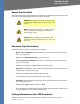
Getting Started How to Use this Guide How to Use this Guide This User Guide has been designed to make understanding networking with the camera easier than ever. Look for the following items when reading this guide: WARNING: This graphic means there is a Warning and is something that could damage your self, property, or the camera. NOTE: This checkmark means there is a Note of interest and is something you should pay special attention to while using the camera.
Getting Started Finding Information in Your PDF Documents • Search an individual PDF • Search multiple PDFs at once (for example, all PDFs in a specific folder or disk drive) • Perform advanced searches Finding Text in a PDF By default, the Find toolbar is open. If it has been closed, choose Edit > Find. Use Find to search for text in an open PDF: 1. Enter your search terms in the Find box on the toolbar. 2.
Getting Started What’s in this Guide? What’s in this Guide? This user guide covers the steps for setting up and using the Wireless-N Gigabit Security Router with VPN. • Chapter 1, "Getting Started" This chapter describes the Wireless-N Gigabit Security Router with VPN applications and this User Guide. It also contains information on how to use this guide. • Chapter 2, "Networking and Security Basics" This chapter describes the basics of networking and network security.
Getting Started What’s in this Guide? • Appendix G, "Warranty Information" This appendix supplies the warranty information for the Router. • Appendix H, "Regulatory Information" This appendix supplies the regulatory information regarding the Router. • Appendix I, "Contact Information" This appendix provides contact information for a variety of Linksys resources, including Technical Support.
Networking and Security Basics An Introduction to LANs Networking and Security Basics An Introduction to LANs A Router is a network device that connects multiple networks together and forward traffic based on IP destination of each packet. The Wireless-N Gigabit Security Router can connect your local area network (LAN) or a group of PCs interconnected in your home or office to the Internet.
Networking and Security Basics The Use of IP Addresses Example network The Use of IP Addresses IP stands for Internet Protocol. Every device in an IP-based network, including PCs, print servers, and routers, requires an IP address to identify its location, or address, on the network. This applies to both the Internet and LAN connections. NOTE: Since the Router is a device that connects two networks, it needs two IP addresses—one for the LAN, and one for the Internet.
Networking and Security Basics The Use of IP Addresses If you use the Router to share your cable or DSL Internet connection, contact your ISP to find out if they have assigned a static IP address to your account. If so, you will need that static IP address when configuring the Router. You can get the information from your ISP. A dynamic IP address is automatically assigned to a device on the network. This IP address is called dynamic because it is only temporarily assigned to the PC or other device.
Networking and Security Basics The Intrusion Prevention System (IPS) The Intrusion Prevention System (IPS) IPS is an advanced technology to protect your network from malicious attacks. IPS works together with your SPI Firewall, IP Based Access List (IP ACL), Network Address Port Translation (NAPT), and Virtual Private Network (VPN) to achieve the highest amount of securities. IPS Scenarios IPS works by providing real-time detection and prevention as an in-line module in a router.
Planning Your Virtual Private Network (VPN) Why do I need a VPN? Planning Your Virtual Private Network (VPN) Why do I need a VPN? Computer networking provides a flexibility not available when using an archaic, paper-based system. With this flexibility, however, comes an increased risk in security. This is why firewalls were first introduced. Firewalls help to protect data inside of a local network.
Planning Your Virtual Private Network (VPN) What is a VPN? Internet. Data travelling over the Internet will often pass through many different servers around the world before reaching its final destination. That's a long way to go for unsecured data and this is when a VPN serves its purpose.
Planning Your Virtual Private Network (VPN) What is a VPN? VPN Router to VPN Router An example of a VPN Router-to-VPN Router VPN would be as follows. At home, a telecommuter uses his VPN Router for his always-on Internet connection. His router is configured with his office's VPN settings. When he connects to his office's router, the two routers create a VPN tunnel, encrypting and decrypting data. As VPNs utilize the Internet, distance is not a factor.
Getting to Know the Router The Front Panel Getting to Know the Router The Front Panel The Router’s LEDs are located on the front panel of the Router. Front of Router Status LED/Color Description Power/ Green The POWER LED lights up when the Router is powered on. The LED flashes when the Router runs a diagnostic test. Diag/ Red The DIAG LED lights up when the system is not ready. The LED light goes off when the system is ready. The Diag LED blinks during Firmware upgrades.
Getting to Know the Router The Front Panel Status LED/Color Description 1-4 (ETHERNET)/ Green For each port, there are three LEDs. If the corresponding LED is continuously lit, the Router is connected to a device at the speed indicated through the corresponding port (1, 2, 3, or 4). The LED flashes when the Router is actively sending or receiving data. INTERNET/ Green The INTERNET LED lights up the appropriate LED depending upon the speed of the device that is attached to the Internet port.
Getting to Know the Router The Back Panel The Back Panel The Router’s ports and Reset button are located on the back panel of the Router. Back of Router Port/Button Description Reset Button The Reset button can be used in one of two ways: If the Router is having problems connecting to the Internet, press the Reset button for just a second with a paper clip or a pencil tip. This is similar to pressing the Reset button on your PC to reboot it.
Getting to Know the Router Antennas and Positions Antennas and Positions The Access Point can be placed in three different positions. It can be either stackable, standalone, or wall-mount.
Getting to Know the Router Antennas and Positions With Mounting Feet The Access Point has three non-detachable 1.8dBi omni-directional antennas. The three antennas have a base that can rotate 90 degrees when in the standing position. The three antennas will all be used to support 2X3 MIMO diversity in wireless-N mode.
Connecting the Router Overview Connecting the Router Overview • To set up your network, you will do the following: • Connect the Router to one of your PCs according to the instructions in this chapter. • By default, Windows 98, 2000, Millennium, and XP computers are set to obtain an IP address automatically, so unless you have changed the default setting, then you will not need to configure your PCs. (If you do need to configure your PCs, refer to Windows Help for more information.
Connecting the Router Connection Instructions Connection Instructions 1. Before you begin, make sure that all of your hardware is powered off, including the Router, PCs, hubs, switches, and cable or DSL modem. 2. Connect one end of an Ethernet network cable to one of the numbered ports on the back of the Router. Connect the other end to an Ethernet port on a network device, e.g., a PC, print server, hub, or switch. 3. Repeat this step to connect more PCs or other network devices to the Router. 4.
Connecting the Router Placement Options 5. Power on the cable or DSL modem and the other network device if using one. 6. Connect the included AC power cable to the Router’s Power port on the side of the Router, and then plug the power adapter into an electrical outlet. The Power LED on the front panel will light up as soon as the power adapter is connected properly. Placement Options There are three ways to place the Wireless-N Router.
Connecting the Router Placement Options Wall-Mount Option You will need two suitable screws to mount the Router. Make sure the screw size can fit into the criss-cross wall-mount slots. 1. On the Wireless Router’s back panel are two criss-cross wall-mount slots. 2. Determine where you want to mount the Wireless Router, and install two screws that are 29/16 in (64.5mm) apart. 3. Line up the Wireless Router so that the wall-mount slots line up with the two screws.
Connecting the Router Placement Options 4. Place the wall-mount slots over the screws and slide the Wireless Router down until the screws fit snugly into the wall-mount slots.
Setting Up and Configuring the Router Overview Setting Up and Configuring the Router Overview The Wireless Router has been designed to be functional right out of the box with the default settings. However, if you'd like to change these settings, the Wireless Router can be configured through your web browser with the Web-based Utility. This chapter explains how to use the Utility to perform the most basic settings.
Setting Up and Configuring the Router How to Navigate the Utility through a DHCP server. It is not recommended, because you can easily lose your connection through wireless configuration changes. To access the Web-based Utility of the Router: 1. Launch a web browser, such as Internet Explorer or Mozilla Firefox, and enter the Router’s default IP address, 192.168.1.1, in the Address field. Press the Enter key. 2. The Connect To screen appears asking you for your User name and Password.
Setting Up and Configuring the Router How to Navigate the Utility • Advanced Routing—Select the Router’s operation mode either connecting to the Internet or Intranet (NAT is only enabled while connecting to the Internet). Configure dynamic or static routing. The Router support RIP version 1 and 2 to automatically exchange routing information and establish its routing table. • Time—Change the time settings on this screen. • IP Mode—Provides options for IPv4 mode or Dual-Stack IPv4 and IPv6 mode.
Setting Up and Configuring the Router How to Navigate the Utility ProtectLink The Trend Micro ProtectLink Gateway hosted service provides security for your network. It checks e-mail messages, filters website addresses (URLs), and blocks potentially malicious websites. VPN You will use VPN tabs to configure VPN tunnels and accounts to establish a secured channel through Internet. • Summary—Displays the Summary of IPSec tunnel Status.
Setting Up and Configuring the Router How to Navigate the Utility IPS Use this tab for advanced configuration on built-in Intrusion Prevention System (IPS) inside the Router. • Configure—Enable or disable IPS functions. • P2P/IM—Allows or blocks specific Peer to Peer (P2P) networks and Instant Messaging (IM) applications. • Report—Provides reports of network traffic and malicious attacks. • Information—Provides the signature file version and the Protection Scope of the IPS system.
Setting Up and Configuring the Router Setup Tab Setup Tab The Setup screen contains all of the Router’s basic setup functions. The Router can be used in most network settings without changing any of the default values. Some users may need to enter additional information in order to connect to the Internet through an ISP (Internet Service Provider) or broadband (DSL, cable modem) carrier. Summary System Information Firmware version—Displays the Router's current software version.
Setting Up and Configuring the Router Setup Tab Network Setting Status LAN IP—Displays the IP address of the Router's LAN interface. WAN IP—Displays the IP address of the Router's WAN interface. If this address was assigned using DHCP, click DHCP Release to release the address, or click DHCP Renew to renew the address. Mode—Displays the operating mode, Gateway or Router. DNS 1-2—The IP addresses of the Domain Name System (DNS) server(s) that the Router is using.
Setting Up and Configuring the Router Setup Tab Internet Connection Type The Router supports six connection types. Each WAN Setup screen and available options will differ depending on what kind of connection type you select. Automatic Configuration - DHCP By default, the Router’s Configuration Type is set to Automatic Configuration - DHCP. The Router will get its IP address from a DHCP server of the ISP. Most cable modem ISPs use this option.
Setting Up and Configuring the Router Setup Tab Internet IP Address—The Router’s IP address on the WAN port that can be reached from the Internet. Your ISP will provide you with the IP Address you need to specify here. Subnet Mask—The Router’s Subnet Mask on the WAN port. Your ISP will provide you this information and your IP Address. Default Gateway—Your ISP will provide you with the Default Gateway (Router) to reach the Internet.
Setting Up and Configuring the Router Setup Tab Keep Alive Redial period—TAllows the Router will periodically check your Internet connection. If you are disconnected, then the Router will automatically re-establish your connection. To use this option, click the option next to Keep Alive. In the Redial Period field, you specify how often you want the Router to check the Internet connection. This option is enabled by default and the default Redial Period is 30 seconds.
Setting Up and Configuring the Router Setup Tab the number of minutes you want to have elapsed before your Internet connection terminates in the Max Idle Time field. Use this option to minimize your DSL connection time if it is charged based on time. This option is disabled by default. Keep Alive Redial period—If you select this option, the Router will periodically check your Internet connection. If you are disconnected, then the Router will automatically re-establish your connection.
Setting Up and Configuring the Router Setup Tab your connection. To use this option, click the option next to Keep Alive. In the Redial Period field, you specify how often you want the Router to check the Internet connection. This option is enabled by default and the default Redial Period is 30 seconds. Use this option to minimize your Internet connection response time since it will always be connected.
Setting Up and Configuring the Router Setup Tab in the Max Idle Time field. Use this option to minimize your DSL connection time if it is charged based on time. This option is disabled by default. Keep Alive Redial period—If you select this option, the Router will periodically check your Internet connection. If you are disconnected, then the Router will automatically re-establish your connection. To use this option, click the option next to Keep Alive.
Setting Up and Configuring the Router Setup Tab DDNS The Router offers a Dynamic Domain Name System (DDNS) feature. DDNS lets you assign a fixed host and domain name to a dynamic Internet IP address. It is useful when you are hosting your own website, FTP server, or other server behind the Router. Before you can use this feature, you need to sign up for DDNS service at DynDNS.org or TZO.com. DDNS Service. If your DDNS service is provided by DynDNS.org, then select DynDNS.org from the drop-down menu.
Setting Up and Configuring the Router Setup Tab TZO.com • E-mail Address, TZO Password, and Domain Name—Enter the E-mail Address, Password, and Domain Name of the account you set up with TZO. • Status—The status of the TZO service connection. After entering the necessary information, the Router will advise the DDNS Service of your current WAN (Internet) IP address whenever this address changes. If using TZO, you should NOT use the TZO software to perform this “IP address update”.
Setting Up and Configuring the Router Setup Tab LAN The LAN Setup section allows you to change the Router’s local network settings for the four Ethernet ports. IPv4 The Router’s Local IPv4 Address and Subnet Mask are shown here. In most cases, you can keep the defaults. Local IP Address—Enter the IPv4 address on the LAN side. The default value is 192.168.1.1. Subnet Mask—Select the subnet mask from the drop-down menu. The default value is 255.255.255.0.
Setting Up and Configuring the Router Setup Tab IP Reserved for Internal Usage—Enter the reserved IP between 1 and 254. Server Settings (DHCP) The Router can be used as your network’s DHCP (Dynamic Host Configuration Protocol) server, which automatically assigns an IP address to each PC on your network. Unless you already have one, it is highly recommended that you leave the Router enabled as a DHCP server. DHCP Server—DHCP is enabled by default.
Setting Up and Configuring the Router Setup Tab DHCP address range end—Enter the ending DHCP v6 IP address. Primary DNS—Enter the Primary IPv6 DNS server address. Secondary DNS—Enter the Secondary IPv6 DNS server address. Click the Save Settings button to save the network settings or click the Cancel Changes button to undo your changes. DMZ The DMZ screen allows one local PC to be exposed to the Internet for use of a special-purpose service, such as Internet gaming and video-conferencing.
Setting Up and Configuring the Router Setup Tab change the registered MAC address to the Router's MAC address. The Router's MAC address is a 6-byte hexadecimal number assigned to a unique piece of hardware for identification. Mac Address Clone—Select Enabled or Disabled. The default is Enabled. Mac Address—Enter the MAC Address registered with your ISP in this field.
Setting Up and Configuring the Router Setup Tab Advanced Routing Operating Mode Select the Operating mode in which the Router will function. Gateway—This is the normal mode of operation. This allows all devices on your LAN to share the same WAN (Internet) IP address. In the Internet Gateway mode, the NAT (Network Address Translation) mechanism is enabled. Router—You either need another Router to act as the Internet Gateway, or all PCs on your LAN must be assigned (fixed) Internet IP addresses.
Setting Up and Configuring the Router Setup Tab Static Routing Some ISPs require static routes to build your routing table instead of using dynamic routing protocols. Static routes do not require CPU resources to exchange routing information with a peer router. You can also use static routes to reach peer routers that do not support dynamic routing protocols. Static routes can be used together with dynamic routes. Be careful not to introduce routing loops in your network.
Setting Up and Configuring the Router Setup Tab Click the Save Settings button to save the Routing settings, click the Cancel Changes button to undo your changes or click the Show Routing Table button to view the current routing table. Time You can either define your Router’s time manually or automatically through Time Server. The default is Automatically.
Setting Up and Configuring the Router Setup Tab Click the Save Settings button to save the Routing settings, click the Cancel Changes button to undo your changes or click the Show Routing Table button to view the current routing table. IP Mode IPv4 Only—Select this option to use IPv4 on the Internet and local network. Dual-Stack IP—Select this option to use IPv4 on the Internet and IPv4 and IPv6 on the local network.
Setting Up and Configuring the Router Wireless Tab Click the Save Settings button to save the network settings or click the Cancel Changes button to undo your changes. Help information is displayed on the right-hand side of the screen, and click More for additional details. Wireless Tab Basic Wireless Settings Change the basic wireless network settings on this screen. Basic Settings Configure the basic Wireless Network attributes for this Wireless Router.
Setting Up and Configuring the Router Wireless Tab Wireless Channel—Select the appropriate channel to be used between your Wireless Router and your client devices. The default is channel 6. You can also select Auto so that your Wireless Router will select the channel with the lowest amount of wireless interference while the system is booting up.
Setting Up and Configuring the Router Wireless Tab Disabled To disable wireless security completely, select Disabled. WEP This security mode is defined in the original IEEE 802.11. This mode is not recommended now due to its weak security protection. Users are urged to migrate to WPA or WPA2. Authentication Type. Choose the 802.11 authentication type as either Open System or Shared Key. The default is Open System.
Setting Up and Configuring the Router Wireless Tab Key 1-4—If you want to manually enter WEP keys, then complete the fields provided. Each WEP key can consist of the letters “A” through “F” and the numbers “0” through “9”. It should be 10 characters in length for 64-bit encryption or 26 characters in length for 128-bit encryption. Tx Key—Select one of the keys to be used for data encryption (when you manually enter multiple WEP keys).
Setting Up and Configuring the Router Wireless Tab WPA2-Personal Encryption—WPA2 always uses AES for data encryption. Shared Key—Enter a WPA Shared Key of 8-63 characters. Key Renewal—Enter a Key Renewal Timeout period, which instructs the Wireless Router how often it should change the encryption keys. The default is 3600 seconds. WPA2-Personal Mixed This security mode supports the transition from WPA-Personal to WPA2-Personal. You can have client devices that use either WPA-Personal or WPA2-Personal.
Setting Up and Configuring the Router Wireless Tab WPA-Enterprise This option features WPA used in coordination with a RADIUS server for client authentication. (This should only be used when a RADIUS server is connected to the Wireless Router.) Encryption—WPA offers you two encryption methods, TKIP and AES for data encryption. Select the type of algorithm you want to use, TKIP or AES. The default is TKIP. RADIUS Server—Enter the RADIUS server’s IP address.
Setting Up and Configuring the Router Wireless Tab WPA2-Enterprise This option features WPA2 used in coordination with a RADIUS server for client authentication. (This should only be used when a RADIUS server is connected to the Wireless Router.) Encryption—WPA2 always uses AES for data encryption. RADIUS Server—Enter the RADIUS server’s IP address. RADIUS Port—Enter the port number used by the RADIUS server. The default is 1812.
Setting Up and Configuring the Router Wireless Tab WPA2-Enterprise Mixed This security mode supports the transition from WPA-Enterprise to WPA2-Enterprise. You can have client devices that use either WPA-Enterprise or WPA2-Enterprise. The Wireless Router will automatically choose the encryption algorithm used by each client device. Encryption—Mixed Mode automatically chooses TKIP or AES for data encryption. RADIUS Server—Enter the RADIUS server’s IP address.
Setting Up and Configuring the Router Wireless Tab Wireless Connection Control Configure the Connection Control List to either permit or block specific wireless client devices connecting to (associating with) the Wireless Router. Select SSID—Select the desired SSID. Enabled/Disabled—Enable or disable wireless connection control. The default is Disabled. Connection Control There are two ways to control the connection (association) of wireless client devices.
Setting Up and Configuring the Router Wireless Tab Advanced Wireless Settings Configure the advanced settings for the Wireless Router. The Wireless-N Router adopts several new parameters to adjust the channel bandwidth and guard intervals to improve the data rate dynamically. Linksys recommends to let your Wireless Router automatically adjust the parameters for maximum data throughput. Advanced Wireless You can change the following advanced parameters (some only for Wireless-N) for this Wireless Router.
Setting Up and Configuring the Router Wireless Tab DTIM Interval—Indicates how often the Wireless Router sends out a Delivery Traffic Indication Message (DTIM). Lower settings result in more efficient networking, while preventing your PC from dropping into power-saving sleep mode. Higher settings allow your PC to enter sleep mode, thus saving power, but interferes with wireless transmissions. The default is 1 ms.
Setting Up and Configuring the Router Firewall Tab different types of traffic. It automatically maps the incoming packets to the appropriate queues based on QoS settings (in IP or layer 2 header). WMM provides the capability to prioritize traffic in your environment. The default is Enabled. Change these settings as described here and click Save Settings to apply your changes, or click Cancel Changes to cancel your changes. Help information is displayed on the right-hand side of the screen.
Setting Up and Configuring the Router Firewall Tab Note that for WAN traffic, NAPT settings are applied first, then the SPI Firewall settings, followed by IP based Access List (which requires more CPU power). Basic Settings Firewall: SP—(Stateful Packet Inspection) Firewall, when you enable this feature, the Router will perform deep packet inspection on all the traffic going through the Router and drop the packets that do not follow the pre-defined protocol behavior. The default is Enable.
Setting Up and Configuring the Router Firewall Tab • Cookies—A cookie is data stored on your PC and used by Internet sites when you interact with them, so you may not want to deny cookies. • ActiveX—ActiveX is a Microsoft (Internet Explorer) programming language for websites. If you deny ActiveX, you run the risk of not having access to Internet sites using this programming language. Also, Windows Update uses ActiveX, so if this is blocked, Windows update will not work.
Setting Up and Configuring the Router Firewall Tab Priority—Defines the order on which rule is checked against first. The smaller number has higher priority. The default rules will always be checked last. Enable—Tells the Router if the rule is active or not. You can have rules defined in the ACL Table but in an inactive state. The administrator can decide on when to enable specific ACL rules manually. Action—Defines how the rule is to affect the traffic. It can be either Allow or Deny.
Setting Up and Configuring the Router Firewall Tab Edit IP ACL Rule This Web page can be entered only through IP Based ACL Tab. Enter this page by clicking Add New Rule button on that page. Action—Select either Allow or Deny. Default is Allow. Service—Select ALL or pre-defined (or user-defined) services from the drop-down menu. Log—If checked, this ACL rule will be logged when a packet match happens. Log Prefix—This string will be attached in front of the log for the matched event.
Setting Up and Configuring the Router Firewall Tab Date—Enter the days in a week this rule will be applied (used together with Time). It can be set to Any Day. Change these settings as described here and click Save Settings to apply your changes, or click Cancel Changes to cancel your changes. Help information is displayed on the right-hand side of the screen, and click More for additional details. Internet Access Policy Access to the Internet can be managed by policies.
Setting Up and Configuring the Router Firewall Tab Use the settings on this screen to establish an access policy. Selecting a policy from the dropdown menu will display that policy's settings. You can then perform the following operations: • Create a Policy—see instructions below. • Delete the current policy—click the Delete button. • View all policies—click the Summary button. On the Summary screen, the policies are listed with the following information: No.
Setting Up and Configuring the Router Firewall Tab To create an Internet Access policy: 1. Select the desired policy number from the Internet Access Policy drop-down menu. 2. Enter a Policy Name in the field provided. 3. Enable this policy by clicking the Enable option. 4. Click the Edit List of PCs button to select which PCs will be affected by the policy. The List of PCs screen appears in a sub-window. You can select a PC by MAC Address or IP Address.
Setting Up and Configuring the Router Firewall Tab the Internet, the NAT Router will forward those requests to the appropriate servers on your LAN. Application—Enter the name of the application you wish to configure. External Port—Port number used by the service or Internet application. Internet users must connect using this port number. Check with the software documentation of the Internet application for more information.
Setting Up and Configuring the Router Firewall Tab Change these settings as described here and click Save Settings to apply your changes, or click Cancel Changes to cancel your changes. Help information is displayed on the right-hand side of the screen, and click More for additional details. Port Range Forwarding This is one of the NAPT (Network Address Port Translation) features.
Setting Up and Configuring the Router Firewall Tab Change these settings as described here and click Save Settings to apply your changes, or click Cancel Changes to cancel your changes. Help information is displayed on the right-hand side of the screen, and click More for additional details. Port Range Triggering This is one of the NAPT (Network Address Port Translation) features. Port Range Triggering is used for special applications that can request a port to be opened on demand.
Setting Up and Configuring the Router ProtectLink Tab ProtectLink Tab The Trend Micro ProtectLink Gateway service provides security for your network. It checks email messages, filters website addresses (URLs), and blocks potentially malicious websites. For detailed information on how to configure the ProtectLink Service, go to Appendix J, "Trend Micro ProtectLink Gateway Service". VPN Tab Summary The IPSec VPN Summary displays a status of the IPSec tunnel status.
Setting Up and Configuring the Router VPN Tab Tunnels Used—Displays the number of tunnels used. Tunnel(s) Available—Displays the number of available tunnels. Detail button—Click Detail to display more tunnel information. Tunnel Status No—Displays the number of the tunnel. Name—Displays the name of the tunnel, as defined by the Tunnel Name field on the VPN > IPSec VPN screen. Status—Displays the tunnel's status: Connected, Hostname Resolution Failed, Resolving Hostname, or Waiting for Connection.
Setting Up and Configuring the Router VPN Tab IPSec VPN Virtual Private Network (VPN) is a security measure that creates a secure connection between two remote locations. Configure these settings so the Gateway will create VPN tunnels. IPSec VPN Tunnel Select Tunnel Entry—Select a tunnel to configure. Delete—Deletes all settings for the selected tunnel. Summary—Shows the settings and status of all enabled tunnels. IPSec VPN Tunnel—Check the Enable option to enable this tunnel.
Setting Up and Configuring the Router VPN Tab Local Security Group Type—Select the local LAN user(s) behind the router that can use this VPN tunnel. This may be a single IP address or Sub-network. Notice that the Local Secure Group must match the other router's Remote Secure Group. IP Address—Enter the IP address on the local network. Subnet Mask—If the "Subnet" option is selected, enter the mask to determine the IP addresses on the local network.
Setting Up and Configuring the Router VPN Tab IPSec Setup Keying Mode—The router supports both IKE with Preshared Key (automatic) and Manual key management. When choosing automatic key management, IKE (Internet Key Exchange) protocols are used to negotiate key material for SA. If manual key management is selected, no key negotiation is needed. Basically, manual key management is used in small static environments or for troubleshooting purpose.
Setting Up and Configuring the Router VPN Tab Encryption— The Encryption method determines the length of the key used to encrypt/ decrypt ESP packets. 3DES is supported. Notice that both sides of the VPN tunnel must use the same Encryption method. Authentication— Authentication determines a method to authenticate the ESP packets. Either MD5 or SHA1 may be selected. Notice that both sides (VPN endpoints) must use the same Authentication method.
Setting Up and Configuring the Router VPN Tab VPN Client Accounts Use this page to administer your VPN Client users. Enter the information at the top of the screen and the users you've entered appear in the list at the bottom, showing their status. This will work with the Linksys QuickVPN client only. (The Router supports up to five Linksys QuickVPN Clients by default. Additional QuickVPN Client licenses can be purchased separately. See www.linksys.com for more information.
Setting Up and Configuring the Router VPN Tab Username—Displays the username. Edit button—Modify the username, password, or toggle between whether the user is allowed to change their password. Remove button—Delete a user account. Certificate Management Use this section to manage the certificate used for securing the communication between the router and QuickVPN clients. Generate—Click this button to generate a new certificate to replace the existing certificate on the router.
Setting Up and Configuring the Router VPN Tab VPN Passthrough This screen allows users to use their own VPN algorithms to connect to their remote Routers. The Wireless Router will just pass the traffic through. IPsec Passthrough—Internet Protocol Security (IPsec) is a suite of protocols used to implement secure exchange of packets at the IP layer. IPsec Passthrough is enabled by default to allow IPsec tunnels to pass through the Router. To disable IPsec Passthrough, select Disabled.
Setting Up and Configuring the Router QoS Tab QoS Tab QoS (Quality of Service) allows you to perform Bandwidth Management, by either Rate Control or Priority. You can also configure QoS Trust Mode and the DSCP settings. Bandwidth Management Bandwidth Specify the maximum bandwidth provided by the ISP on the WAN interface, for both the upstream and downstream directions. Bandwidth Management Type Type—The desired type of bandwidth management, either Rate Control (default) or Priority.
Setting Up and Configuring the Router QoS Tab Enable—Check this box to enable this Rate Control Rule. Add to list—After a rule is set up, click this button to add it to the list. The list can contain a maximum of 15 entries. Delete selected application—Click this button to delete a rule from the list. Priority Screen Service—Select the service from the drop-down menu. If it does not contain the service you need, click Service Management to add the service.
Setting Up and Configuring the Router QoS Tab QoS Setup The QoS Setup screen allows users to configure QoS Trust Mode for each LAN port. Port ID—The number of the LAN port. Trust Mode—Select either Port, CoS, or DSCP. The default is Port. Default CoS/Port Priority—If Trust Mode is set to Port, select the port priority from 1 to 4 from the drop-down menu. If Trust Mode is set to CoS, select the default CoS priority from 0 to 7 from the drop-down menu. CoS Setup Priority—The CoS priority from 0 to 7.
Setting Up and Configuring the Router QoS Tab DSCP Setup DSCP—The Differentiated Services Code Point value in the incoming packet. Queue—Select the traffic forwarding queue, to 4, to which the DSCP priority is mapped. Restore Defaults—Click this button to restore the default DSCP values. Change these settings as described here and click Save Settings to apply your changes, or click Cancel Changes to cancel your changes.
Setting Up and Configuring the Router Administration Tab Administration Tab Management Router Access This configures the administrator user accounts to manage the Wireless Router through Web based Utility. Only the first user is created by default. Other accounts are not created by default so you can leave them alone. Make sure to change the first user account username and password when you configure your Wireless Router for the first time.
Setting Up and Configuring the Router Administration Tab SNMP Configures the Simple Network Management Protocol settings. Users can use management software to read or write information from or to the device. SNMP—Select Enable if you wish to use SNMP. To use SNMP, you need SNMP software on your PC. System Name—Enter a suitable name. This name will be used to identify this device, and will be displayed by your SNMP software. System Contact—Enter contact information for the system.
Setting Up and Configuring the Router Administration Tab configure the Wireless Router to send the event log to you through e-mail, upload the log to syslog server, or view the log locally on the Wireless Router. Log Setting Log Level—Select the log level(s) that the Router should record. Log levels and their meanings are described in the left table.
Setting Up and Configuring the Router Administration Tab Level Severity Name Description 0 LOG_EMERG System unusable Outgoing Log—Select Enable to cause all outgoing packets to be logged. You can then click View Outgoing Table to display information on the outgoing packets including Source IP, Destination IP, and Service/Port number. Incoming Log—Select Enable to cause all incoming packets to be logged.
Setting Up and Configuring the Router Administration Tab Local Log—Enable this if you want to see the log locally on the Wireless Router. View Log button—If Local Log is enabled, click View Log to view the event log on the Wireless Router. Change these settings as described here and click Save Settings to apply your changes, or click Cancel Changes to cancel your changes. Help information is displayed on the right-hand side of the screen, and click More for additional details.
Setting Up and Configuring the Router Administration Tab Diagnostics Ping Test Parameters Ping Target IP—Enter the IP address or URL that you want to ping. Ping Size—Enter the size of the packet you want to use. Number of Pings—Enter the number of times you wish to ping the target device. Ping Interval—Enter the time period (in milliseconds) between each ping. Ping Timeout—Enter the desired time period (in milliseconds).
Setting Up and Configuring the Router Administration Tab Start Test button—Click this button to begin the test. A new screen appears and display the test results. A summary of the PING results will be shown on the bottom of this screen. Ping Result. Displays the Ping status results. Traceroute Test Parameters TraceRoute Target—Enter the IP address or Host name to perform the traceroute testing. Start Test button—Click this button to begin the test. A new screen appears and display the test results.
Setting Up and Configuring the Router Administration Tab Status—Displays the status of the pair. Change these settings as described and click Save Settings to apply your changes, or click Cancel Changes to cancel your changes. Help information is displayed on the right-hand side of the screen, and click More for additional details. Backup & Restore Backup Backup button. To download a copy of the current configuration and store the file on your PC, click Backup to start the download.
Setting Up and Configuring the Router Administration Tab Factory Defaults Restore Factory Defaults—Click this button to reset all configuration settings to their default values—All settings that have been saved will be lost when the default settings are restored. After clicking the button, another screen appears. Click OK to continue. Another screen appears while the system reboots. Reboot Reboot—Click this button to reboot the Router.
Setting Up and Configuring the Router Administration Tab Firmware Upgrade To upgrade firmware, download the latest firmware for the product from Linksys.com, extract it to your computer, and perform the steps below: 1. File—Type in the name of the extracted firmware upgrade file or click Browse to locate the file from the file system. 2. Start to Upgrade—When you have selected the appropriate file, click the Start to Upgrade button and follow the on-screen instructions to upgrade your firmware.
Setting Up and Configuring the Router IPS Tab IPS Tab The Wireless Router supports advanced Intrusion Prevention Systems (IPS), which is an integral part of the self-defending strategy—It allows you to stay current on the latest threats so that malicious or damaging traffic is accurately identified, classified, and stopped in realtime. You can use IPS together with Firewall, IP based ACL, and IPsec VPN to achieve maximum securities. The IPS is hardware-accelerated on this Wireless Router.
Setting Up and Configuring the Router IPS Tab Change these settings as described here and click Save Settings to apply your changes, or click Cancel Changes to cancel your changes. Help information is displayed on the right-hand side of the screen, and click More for additional details. P2P/IM This tab allows the system administrator to set up policies on using P2P or IM software across the Internet.
Setting Up and Configuring the Router IPS Tab Report This screen provides the network history status, including network traffic and attack counts, through diagram and tables. Report Diagram—Twenty-four hour diagram displays network traffic and attacks. Attacker Displays the IP Address of attackers and the frequency (number of times) of the attacks in a table. Attacked Category Displays the category (type) of attack and the frequency (number of times) of the attacks in a table.
Setting Up and Configuring the Router L2 Switch Tab Click the View Log button to view the log. Information Signature Version—The Signature Version displays the version of the signature patterns file loaded in the Wireless Router that protects against malicious threats. Last Time Upload—Displays when the signature patterns file in the Wireless Router were last updated. Protect Scope—Displays a list of the categories of attacks that the IPS feature in the Router protects against.
Setting Up and Configuring the Router L2 Switch Tab network traffic to flow more efficiently within subgroups. VLANs managed through software reduce the amount of time in which network changes are implemented. VLANs have no minimum number of ports, and can be created per unit, per device, per stack, or any other logical connection combination, as VLANs are software based and not defined by physical attributes. VLANs function at layer 2.
Setting Up and Configuring the Router L2 Switch Tab VLAN & Port Assignment This Tab is a combination of Port settings and VLAN membership tabs in one on this device and other routers. The first section is port specific settings regarding the use of VLAN (nothing to do with individual VLANs). It requires users to specify the port mode for each port.
Setting Up and Configuring the Router L2 Switch Tab • General—All frames can be tagged or untagged coming in to the switch. If it is untagged, default PVID will apply to the packet. Only the General mode users can choose the following two options. NOTE: The following cannot be supported on Vitesse 7385 switch chipset • – Acceptable Ingress Frame Type—All Frames: all the incoming frames are acceptable.
Setting Up and Configuring the Router L2 Switch Tab RADIUS RADIUS mode provides authentication on devices connecting to the LAN ports. It requires installation of a RADIUS server on your local network. Mode—Select Enabled or Disabled, as desired. RADIUS IP—Enter the RADIUS server IP address. RADIUS UDP Port—Identifies the UDP port. The UDP port is used to verify the RADIUS server authentication.
Setting Up and Configuring the Router L2 Switch Tab Port Settings Port—Specifies the number of the four LAN ports. Link—Displays the port duplex mode (Full or Half ) and speed (10/100/1000 Mbps). Full indicates that the interface supports transmission between the device and its link partner in both directions simultaneously. Half indicates that the interface supports transmission between the device and the client in only one direction at a time.
Setting Up and Configuring the Router L2 Switch Tab Statistics Overview Tx Bytes—Displays the number of Bytes transmitted from the selected port. Tx Frames—Displays the number of Frames transmitted from the selected port. Rx Bytes—Displays the number of Bytes received on the selected port. Rx Frames—Displays the number of Frames received on the selected port. Tx Errors—Displays the number of error packets transmitted from the selected port.
Setting Up and Configuring the Router L2 Switch Tab Mirror Port—Select the mirror destination port from the drop-down menu. RSTP The RSTP (Rapid Spanning Tree Protocol) protocol prevents loops in the network and dynamically reconfigures which physical links in a switch should forward frames. System Priority—Enter the system priority from 0 to 61440 in increments of 4096. Valid values are 0, 4096, 8192, 12288, 16384, 20480, 24576, 28672, 32768, 40960, 45056, 49152, 53248, 57344, and 61440.
Setting Up and Configuring the Router Status Tab Status Tab The Status Tab provides current status on this Wireless Router including WAN, LAN, Wireless LAN, System Performance, VPN client connections, and IPsec VPN connections. WAN / Gateway This screen provides some basic information on the Wireless Router (e.g. firmware version, time) and WAN port MAC/IP address and connection status. Firmware Version—Displays the current firmware version.
Setting Up and Configuring the Router Status Tab DHCP Renew button—Click this button to renew IP address on the WAN port if using DHCP. IP Conntrack—Click this button to display the IP Conntrack screen. The IP Conntrack (Connection Tracking) screen displays information about TCP/UDP connections, such as source and destination IP address and port number pairs (known as socket pairs), protocol types (TCP/UDP/ICMP), connection state and timeouts.
Setting Up and Configuring the Router Status Tab IPv6 Address—Displays the LAN port IPv6 IP address, if IPv6 is enabled. DHCP Server—Displays the status of the Router's DHCP server. Start IP Address—Displays the beginning of the range of IP addresses used by the DHCP Server. End IP Address—Displays the end of the range of IP addresses used by the DHCP Server.
Setting Up and Configuring the Router Status Tab Wireless LAN This screen provides some basic information on the Wireless LAN of this Wireless Router. Wireless IP Address— The IP address assigned to the wireless interface of this router. MAC Address—Displays the MAC address on the Wireless LAN interface. Network Mode—Displays the Wireless network operating mode (e.g. B/G/N-Mixed). Wireless SSID—Displays the Wireless network name. Channel Bandwidth—Displays the wireless channel bandwidth setting.
Setting Up and Configuring the Router Status Tab System Performance This screen provides data packet statistics on the LAN switch and Wireless LAN of the Router. All LAN Ports / WLAN The All LAN Ports column shows the aggregate traffic statistics from all four LAN ports. Packets Received—Shows the number of packets received. Packets Sent—Shows the number of packets sent. Bytes Received—Shows the number of bytes received. Bytes Sent—Shows the number of bytes sent.
VPN Setup Wizard 7 Before You Begin VPN Setup Wizard Now you can configure a gateway-to-gateway VPN tunnel between two VPN routers in a fast and efficient way by using the VPN Setup Wizard. The VPN Setup Wizard works with users running Microsoft Windows 2000, XP, and Vista. This document describes how to run the VPN Setup Wizard. Before You Begin The VPN Setup Wizard works with the following routers: • Linksys RVS4000 4-Port Gigabit Security Router with VPN • Linksys WRVS4400N v1.
VPN Setup Wizard Running the VPN Router Software Wizard Running the VPN Router Software Wizard 1. Access the VPN Setup Wizard in one of two ways: • If you have an RVS4000, WRVS4400N v1.1, or WRVS4400N v2 Installation CD-ROM, insert it into your CD-ROM drive. • Download the VPN Setup Wizard from the Linksys Support site for your router. 2. Go to the Start menu and click Run. In the field provided, enter D:\VPN Setup Wizard.exe 3. The Welcome screen appears. Click the Click Here to Start button.
VPN Setup Wizard Running the VPN Router Software Wizard 4. A informational screen discussing the VPN Wizard appears. When you are ready, click Next to proceed. 5. The Choose a way to build VPN screen appears. • If your PC is local to one of the two routers, choose Build VPN connection from Local LAN port of one router, click Next, and continue with these instructions. • If your PC is remote to the routers, choose Build VPN connection from Internet remotely.
VPN Setup Wizard Running the VPN Router Software Wizard 6. If you picked Build VPN connection from Local LAN port of one router, enter the required data in the Configure VPN Tunnel screen and click Next to continue. • Router 1 User Name: Enter the user name of the Router 1. • Router 1 Password: Enter the password of the Router 1. • Router 2 User Name: Enter the user name of the Router 2. • Router 2 Password: Enter the password of the Router 2. • Tunnel Name: Enter a name for this tunnel.
VPN Setup Wizard Running the VPN Router Software Wizard 7. The router configuration is checked. 8. The Summary screen appears. Use the Click box to view the VPNC Summary screen.
VPN Setup Wizard Running the VPN Router Software Wizard 9. The VPNC Summary screen appears showing the settings that were made to industry standards. Click Close when you are ready to continue. 10. In the Summary screen, if all your entries appear correct, click Go. Otherwise click Back to go back and make any corrections.
VPN Setup Wizard Running the VPN Router Software Wizard 11. Click Testing to make sure the connection is successfully established. 12. When testing is done, click Exit to end the Wizard. Congratulations! Setup is now complete. You may now log into the Web Administrator Interface and see the results.
VPN Setup Wizard Running the VPN Router Software Wizard WRVS4400N User Guide 114
VPN Setup Wizard Running the VPN Router Software Wizard Building Your VPN Connection Remotely This procedure continues from Step 5. Use this procedure to build your VPN connection from a remote PC. 1. Choose Build VPN connection from Internet remotely. Click Next to continue.
VPN Setup Wizard Running the VPN Router Software Wizard 2. Enter the required data in the Configure VPN Tunnel screen and then click Next to continue. • Router 1 User Name: Enter the user name of the Router 1. • Router 1 Password: Enter the password of the Router 1. • Router 2 User Name: Enter the user name of the Router 2. • Router 2 Password: Enter the password of the Router 2. • Tunnel Name: Enter a name for this tunnel.
VPN Setup Wizard Running the VPN Router Software Wizard 3. The router configuration is checked. 4. The Summary screen appears. Use the Click box to view the VPNC Summary screen.
VPN Setup Wizard Running the VPN Router Software Wizard 5. The VPNC Summary screen appears showing the settings that were made to industry standards. Click Close when you are ready to continue. 6. In the Summary screen, if all your entries appear correct, click Go. Otherwise click Back to go back and make any corrections.
VPN Setup Wizard Running the VPN Router Software Wizard 7. Click Testing to make sure the connection is successfully established. 8. When testing is done, click Exit to end the Wizard.
VPN Setup Wizard Running the VPN Router Software Wizard Congratulations! Setup is now complete. You may now log into the Web Administrator Interface and see the results.
Common Problems and Solutions Troubleshooting This appendix provides solutions to problems that may occur during the installation and operation of the Router. Read the descriptions below to help solve your problems. If you can't find an answer here, check the Linksys website at www.linksys.com. Common Problems and Solutions I need to set a static IP address on a PC. The Router, by default, assigns an IP address range of 192.168.1.100 to 192.168.1.149 using the DHCP server on the Router.
Common Problems and Solutions 3. In the Components checked are used by this connection box, highlight Internet Protocol (TCP/IP), and click the Properties button. Select Use the following IP address option. 4. Enter a unique IP address that is not used by any other computer on the network connected to the Router. You can only use an IP address in the ranges 192.168.1.2 to 192.168.1.99 and 192.168.1.151 to 192.168.1.254. 5. Enter the Subnet Mask, 255.255.255.0. 6. Enter the Default Gateway, 192.168.1.
Common Problems and Solutions Check your TCP/IP settings. For Windows 98 and Millennium: Refer to Windows Help for details. Make sure Obtain IP address automatically is selected in the settings. For Windows 2000: 1. Click Start, Settings, and Control Panel. Double-click Network and Dial-Up Connections. 2. Right-click the Local Area Connection that is associated with the Ethernet adapter you are using, and select the Properties option. 3.
Common Problems and Solutions 1. In the command prompt, type ping 192.168.1.1 and press the Enter key. • If you get a reply, the computer is communicating with the Router. • If you do NOT get a reply, check the cable, and make sure Obtain an IP address automatically is selected in the TCP/IP settings for your Ethernet adapter. 2. In the command prompt, type ping followed by your Internet IP address and press the Enter key. The Internet IP Address can be found in the web interface of the Router.
Common Problems and Solutions 1. Refer to “Problem #2, I want to test my Internet connection” to verify that your computer is properly connected to the Router. 2. Refer to “Appendix E: Finding the MAC Address and IP Address for Your Ethernet Adapter” to verify that your computer has an IP Address, Subnet Mask, Gateway, and DNS. 3. Set a static IP address on your system; refer to “Problem #1: I need to set a static IP address.” 4.
Common Problems and Solutions 1. Access the Router’s Web-based Utility by going to http://192.168.1.1 or the IP address of the Router. Go to the Firewall => Single Port Forwarding tab. 2. Enable one of the pre-defined applications in the Table or you can add or modify existing entries for your application. 3. Enter the IP Address of the server that you want the Internet users to access. For example, if the web server’s Ethernet adapter IP address is 192.168.1.100, you would enter 100 in the field provided.
Common Problems and Solutions Application Start and End Protocol IP Address Enabled Halflife 27015 to 27015 Both 192.168.1.105 X PC Anywhere 5631 to 5631 UDP 192.168.1.102 X VPN IPSEC 500 to 500 UDP 192.168.1.100 X 4. Configure as many entries as you like. 5. When you have completed the configuration, click the Save Settings button. I can’t get the Internet game, server, or application to work.
Common Problems and Solutions 4. Click the Save Settings button. I am a PPPoE user, and I need to remove the proxy settings or the dial-up pop-up window. If you have proxy settings, you need to disable these on your computer. Because the Router is the gateway for the Internet connection, the computer does not need any proxy settings to gain access. Please follow these directions to verify that you do not have any proxy settings and that the browser you use is set to connect directly to the LAN.
Common Problems and Solutions 1. Use the Linksys TFTP program to upgrade the firmware. Go to the Linksys website at http://www.linksys.com and download the TFTP program, which will be listed with the firmware. 2. Set a static IP address on the PC; refer to “Problem #1, I need to set a static IP address.” Use the following IP address settings for the computer you are using: – IP Address: 192.168.1.50 – Subnet Mask: 255.255.255.0 – Gateway: 192.168.1.1 3. Perform the upgrade using the TFTP utility.
Common Problems and Solutions If your difficulties continue, change the Size to different values. Try this list of values, one value at a time, in this order, until your problem is solved: – 1462 – 1400 – 1362 – 1300 I need to use port triggering. Port triggering looks at the outgoing port services used and will trigger the Router to open a specific incoming port, depending on which port an Internet application uses. Follow these steps: 1.
Frequently Asked Questions Preferences, Advanced, and Proxy. Make sure that Netscape Navigator is set to Direct connection to the Internet. I’m trying to access the Router’s Web-based Utility, but I do not see the login screen. Instead, I see a screen saying, “404 Forbidden.” If you are using Windows Explorer, perform the following steps until you see the Web-based Utility’s login screen (Netscape Navigator will require similar steps): 1. Click File. Make sure Work Offline is NOT checked. 2.
Frequently Asked Questions Yes, but Linksys does not, at this time, provide technical support for setup, configuration or troubleshooting of any non-Windows operating systems. I set up an Unreal Tournament Server, but others on the LAN cannot join. What do I need to do? If you have a dedicated Unreal Tournament server running, you need to create a static IP for each of the LAN computers and forward ports 7777, 7778, 7779, 7780, 7781, and 27900 to the IP address of the server.
Frequently Asked Questions firmware version, unless that version contains new features that you would like to use. Downloading a more current version of Router firmware will not enhance the quality or speed of your Internet connection, and may disrupt your current connection stability. Will the Router function in a Macintosh environment? Yes, but the Router’s setup pages are accessible only through Internet Explorer 5.0 or Netscape Navigator 5.0 or higher for Macintosh.
Frequently Asked Questions The maximum number depends on many factors. At least one IPSec session will work through the Router; however, simultaneous IPSec sessions may be possible, depending on the specifics of your VPNs. How can I check whether I have static or DHCP IP addresses? Ask your ISP to find out. How do I get mIRC to work with the Router? Under the Firewall => Single Port Forwarding tab, set port forwarding to 113 for the PC on which you are using mIRC.
Overview Linksys QuickVPN Software Overview The Linksys Wireless-N Gigabit Security Router with VPN offers a free QuickVPN software program for computers running Windows 2000 or XP. (Computers running other operating systems will have to use a third-party VPN software program.) This guide describes how to install and use the Linksys QuickVPN software.
Installing the Linksys QuickVPN Software 5. Click the Add/Save button. 6. Click the Active checkbox for VPN Client No. 1. 7. Click the Save Settings button. Installing the Linksys QuickVPN Software Installing from the CD-ROM 1. Click Install QuickVPN and follow the on-screen instructions. Downloading and Installing from the Internet 1. Go to www.linksys.com and select Products. 2. Click Business Solutions. 3. Click Router/VPN Solutions. 4. Click RVS4000. 5.
Using the Linksys QuickVPN Software Using the Linksys QuickVPN Software NOTE: You can change your password only if you have been granted that privilege by your system administrator. 1. Double-click the Linksys QuickVPN software icon on your desktop or in the system tray. 2. The login screen will appear. Enter a name for your profile. a. Enter the User Name and Password you have been assigned. b. In the Server Address field, enter the IP address or domain name of the Router. c.
Using the Linksys QuickVPN Software Connecting Screen Activating Screen Verifying Network 4. When your QuickVPN connection is established, the status screen will appear. 5. The QuickVPN tray icon will turn green. It will display the IP address of the remote end of the VPN tunnel, the time and date the VPN tunnel began, and the total length of time the VPN tunnel has been active. QuickVPN Tray Icon - Connection QuickVPN Tray Icon - No Connection 6.
Using the Linksys QuickVPN Software 7. If you clicked the Change Password button and have permission to change your own password, you will see the Connect Virtual Private Connection screen. 8. Enter your password in the Old Password field. Enter your new password in the New Password field. Then enter the new password again in the Confirm New Password field. Click the OK button to save your new password. Click the Cancel button to cancel your change. For information, click the Help button.
Overview Configuring a Gateway-to-Gateway IPSec Tunnel Overview This appendix explains how to configure an IPSec VPN tunnel between two VPN Routers by example. Two PCs are used to test the liveliness of the tunnel. You can think of the VPN Router1, Internet, VPN Router2 as a big virtual router that connects PC1 on LAN1 and PC2 on LAN2.
Configuring the VPN Settings for the VPN Routers 3. A password request page will appear. (Non-Windows XP users will see a similar screen.) Complete the User Name and Password fields (admin is the default user name and password). Then click the OK button. 4. The main window appears.
Configuring the VPN Settings for the VPN Routers 5. Click the VPN tab. 6. Click the IPSec VPN tab. 7. For the VPN Tunnel setting, select Enabled. 8. Enter a name in the Tunnel Name field. 9. For the Local Secure Group, select Subnet. Enter VPN Router 1’s local network settings in the IP Address and Mask fields. 10. For the Remote Secure Group, select Subnet. Enter VPN Router 2’s local network settings in the IP Address and Mask fields.
Configuring the Key Management Settings Configuring the Key Management Settings Configuring VPN Router 1 Following these instructions for VPN Router 1. 1. On the IPSec VPN screen, select 3DES from the Encryption drop-down menu. 2. Select MD5 from the Authentication drop-down menu. 3. Keep the default Key Exchange Method, Auto(IKE). 4. Select Pre-Shared Key, and enter a string for this key., e.g. 13572468. 5. For the PFS setting, select Enabled. 6.
Configuring PC 1 and PC 2 15. Click the Save Settings button on the IPSec VPN screen. Configuring VPN Router 2 For VPN Router 2, follow the same instructions as you did for configuring VPN Router 1. Configuring PC 1 and PC 2 1. Set PC 1 and PC 2 to be DHCP clients (refer to Windows Help for more information). 2. Verify that PC 1 and PC 2 can ping each other (refer to Windows Help for more information). If the computers can ping each other, then you know the VPN tunnel is configured correctly.
Windows 98 or Me Instructions MAC Address and IP Address This section describes how to find the MAC address for your computer’s Ethernet adapter so you can use the MAC address cloning feature of the Router. You can also find the IP address of your computer’s Ethernet adapter. This IP address is used for the Router’s filtering, forwarding, and/or DMZ features. Follow the steps in this appendix to find the adapter’s MAC or IP address in Windows 98, Me, 2000, or XP. Windows 98 or Me Instructions 1.
Windows 2000 or XP Instructions The following example shows the Ethernet adapter’s IP address as 192.168.1.100. Your computer may show something different. MAC Address/Adapter Address Windows 2000 or XP Instructions 1. Click Start and Run. In the Open field, enter cmd. Press the Enter key or click the OK button. 2. At the command prompt, enter ipconfig /all. Then press the Enter key. Write down the Physical Address as shown on your computer screen. It is the MAC address for your Ethernet adapter.
For the Router’s Web-based Utility MAC Address/Physical Address For the Router’s Web-based Utility For MAC address cloning, enter the MAC Address in the MAC Address field or select Clone My PCs MAC. MAC Address Clone Click Save Settings to save the MAC Cloning settings or click the Cancel Changes button to undo your changes.
Glossary This glossary contains some basic networking terms you may come across when using this product. For more advanced terms, see the complete Linksys glossary at http:// www.linksys.com/glossary. Access Point - A device that allows wireless-equipped computers and other devices to communicate with a wired network. Also used to expand the range of a wireless network.
Domain - A specific name for a network of computers. Download - To receive a file transmitted over a network. DSL (Digital Subscriber Line) - An always-on broadband connection over traditional phone lines. Dynamic IP Address - A temporary IP address assigned by a DHCP server. EAP (Extensible Authentication Protocol) - A general authentication protocol used to control network access. Many specific authentication methods work within this framework.
ISP (Internet Service Provider) - A company that provides access to the Internet. LAN - The computers and networking products that make up your local network. MAC (Media Access Control) Address - The unique address that a manufacturer assigns to each networking device. Mbps (MegaBits Per Second) - One million bits per second; a unit of measurement for data transmission.
SNMP (Simple Network Management Protocol) - A widely used network monitoring and control protocol. SPI (Stateful Packet Inspection) Firewall - A technology that inspects incoming packets of information before allowing them to enter the network. SSID (Service Set IDentifier) - Your wireless network's name. Static IP Address - A fixed address assigned to a computer or device that is connected to a network. Static Routing - Forwarding data in a network via a fixed path.
WEP (Wired Equivalent Privacy) - A method of encrypting network data transmitted on a wireless network for greater security. WLAN (Wireless Local Area Network) - A group of computers and associated devices that communicate with each other wirelessly. WPA (Wi-Fi Protected Access) - a wireless security protocol using TKIP (Temporal Key Integrity Protocol) encryption, which can be used in conjunction with a RADIUS server.
Specifications WRVS4400N v2 Specifications Model WRVS4400Nv2 Standards Draft IEEE802.11n, IEEE802.11g, IEEE802.11b, IEEE802.3, IEEE802.3u, 802.1X (Security Authentication), IEEE802.1Q (VLAN), 802.11i (Security WPA2), 802.
WRVS4400N v2 Specifications VPN 5 QuickVPN Tunnels for remote client access 5 IPSec Gateway-to-Gateway Tunnels for branch office connectivity 3DES Encryption MD5/SHA1 Authentication IPSec NAT-T VPN Passthrough of PPTP, L2TP, IPSec Access Control IP Access Control List (ACL); MAC-based wireless access control Firewall SPI stateful packet inspection (SPI) firewall Content Filtering Static URL blocking or keyword blocking (included), Dynamic Filtering through Trend Micro™ ProtectLink™ Gateway Security
WRVS4400N v2 Specifications Weight 1.01 lbs (0.46kg) Power 12V 1A Certification FCC Class B, ICES-003, CE, WiFi WPA2, WiFi Draft N 2.0 Operating Temp. 0ºC to 40ºC (32ºF to 104ºF) Storage Temp.
LIMITED WARRANTY Warranty Information LIMITED WARRANTY Linksys warrants this Linksys hardware product against defects in materials and workmanship under normal use for the Warranty Period, which begins on the date of purchase by the original end-user purchaser and lasts for the period specified for this product at www.linksys.com/ warranty. The internet URL address and the web pages referred to herein may be updated by Linksys from time to time; the version in effect at the date of purchase shall apply.
Obtaining Warranty Service TO THE EXTENT NOT PROHIBITED BY LAW, IN NO EVENT WILL LINKSYS BE LIABLE FOR ANY LOST DATA, REVENUE OR PROFIT, OR FOR SPECIAL, INDIRECT, CONSEQUENTIAL, INCIDENTAL OR PUNITIVE DAMAGES, REGARDLESS OF THE THEORY OF LIABILITY (INCLUDING NEGLIGENCE), ARISING OUT OF OR RELATED TO THE USE OF OR INABILITY TO USE THE PRODUCT (INCLUDING ANY SOFTWARE), EVEN IF LINKSYS HAS BEEN ADVISED OF THE POSSIBILITY OF SUCH DAMAGES.
FCC Statement Regulatory Information FCC Statement This equipment has been tested and found to comply with the limits for a Class B digital device, pursuant to Part 15 of the FCC Rules. These limits are designed to provide reasonable protection against harmful interference in a residential installation. This equipment generates, uses and can radiate radio frequency energy and, if not installed and used in accordance with the instructions, may cause harmful interference to radio communications.
FCC Statement American National Standards Institute (ANSI) / Institute of Electrical and Electronic Engineers / IEEE C 95.1 (92) International Commission on Non Ionizing Radiation Protection (ICNIRP) 98 Ministry of Health (Canada) Safety Code 6.
Safety Notices This system has been evaluated for RF exposure for Humans in reference to the ICNIRP (International Commission on Non-Ionizing Radiation Protection) limits. The minimum separation distance from the antenna to the user is 20cm (7.9 inches). Explosive Environment, Medical and FAA Device Information Use on Board Aircraft The use of wireless on board aircraft is restricted by certain regulations and airline policy.
Safety Notices User Information for Consumer Products Covered by EU Directive 2002/96/ EC on Waste Electric and Electronic Equipment (WEEE) WARNING: Risk of explosion if battery is replaced by an incorrect type. Dispose of used batteries according to the instructions. This document contains important information for users with regards to the proper disposal and recycling of Linksys products.
Safety Notices WRVS4400N User Guide 162
Safety Notices WRVS4400N User Guide 163
Safety Notices WRVS4400N User Guide 164
Safety Notices WRVS4400N User Guide 165
Safety Notices WRVS4400N User Guide 166
Safety Notices WRVS4400N User Guide 167
Safety Notices For more information, visit www.linksys.com.
US/Canada Contacts Contact Information Need to contact Linksys? For additional information or troubleshooting help, refer to the User Guide on the CD-ROM. Additional support is also available by phone or online. US/Canada Contacts • 24-Hour Technical Support: 866-606-1866 • RMA (Return Merchandise Authorization): http://www.linksys.com/warranty • Website: http://www.linksys.com • FTP Site: ftp://ftp.linksys.com • Support: http://www.linksys.
ProtectLink Trend Micro ProtectLink Gateway Service The optional Trend Micro ProtectLink Gateway service provides security for your network. It checks e-mail messages, filters website addresses (URLs), and blocks potentially malicious websites. (To purchase a license for this service, contact your Linksys reseller.) This appendix explains how to use this service. ProtectLink Click the ProtectLink tab to display this screen.
How to Use the Service I have purchased ProtectLink Gateway and want to register it—If you already have a license, click this link. You will be redirected to the Trend Micro ProtectLink Gateway website. Then follow the on-screen instructions. NOTE: To have your e-mail checked, you will need to provide the domain name and IP address of your e-mail server. If you do not know this information, contact your ISP.
ProtectLink > Web Protection Business Hour Setting Business Days—Select the appropriate days. The default days are Mon. through Fri. Business Times—To specify entire days, keep the default, All day (24 hours). To specify hours, select Specify business hours. For morning hours, select Morning, and then select the appropriate From and To times. For afternoon hours, select Afternoon, and then select the appropriate From and To times.
ProtectLink > Email Protection Temporarily block URL requests (This is the recommended setting)—If there are too many URL requests, the overflow will be held back until they can be processed. This is the default setting. Temporarily bypass Trend Micro URL verification for requested URLs—If there are too many URL requests, the overflow will be allowed without verification. Click Save Settings to save your changes, or click Cancel Changes to undo them.
ProtectLink > License License Information View detailed license online—To view license information online, click this link. Status—The status of your license, Activated or Expired, is displayed. Platform—The platform type, Gateway Service, is automatically displayed. License expires on—The date and time your license expires are displayed. Renew—To renew your license, click Renew. Then follow the on-screen instructions. Add Seats—Each seat allows an e-mail account to use Email Protection.