047200 - DVR BUILT IN LCD MONITOR USER’S MANUAL VER V1.
• INDEX • CHAPTER 1 1. 2. 3. 4.
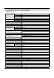
• Specification & Configuration 1. Specification LCD Hardware Type 15.0” TFT LCD Panel Pixel Pitch 0.297mm(H) x 0.
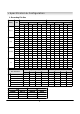
• Specification & Configuration 2. Recording File Size NTSC Quality HDD Highest High Standard Low PAL 720x480/7fps 720x240/15fps 352x240/30fps 704x576/6fps 704x288/12fps 352x288/25fps Hour Day Hour Day Hour Day Hour Day Hour Day Hour Day 80G 40 1.7 37 1.5 41 1.7 42 1.8 40 1.7 48 2.0 120G 60 2.5 57 2.4 62 2.6 67 2.8 62 2.6 72 3.0 160G 79 3.3 74 3.1 82 3.4 89 3.7 84 3.5 96 4.0 200G 98 4.1 94 3.9 103 4.3 110 4.6 105 4.4 120 5.
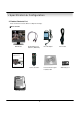
• Specification & Configuration 3. Product Contents List Please Confirm the Contents When You Open the Package.
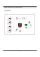
• Specification & Configuration 4.
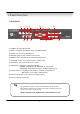
• Panel Function 1. Front Panel ① ② ③ ④ ⑧ ⑩ 1 ⑤ ⑥ ⑦ 2 3 ⑨ 4 ⑪ ① POWER : System Power On/Off ② MENU : Used when changing the menu of SYSTEM SETUP. ③ ENTER : It is used as the SELECT key. ④ RETURN : Cancel setup or return previous mode. ⑤ SEARCH : Go to search mode for searching recorded video. ⑥ SCRMEDE : Select screen division mode or rotation mode.
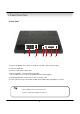
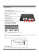
• Panel Function 2. Rear Panel ① ② ③ ④ ⑤ ⑥ ① 8 pin RJ 45 Modular Jack : Video In + Audio In + RS-485 + Camera Power ( Max.) ② Video Out : BNC Out ③ Camera select switch : NTSC / PAL ④ Ethernet (TCP/IP) : Connect Port for LAN Cable (It is possible for user to connect the DVR by Remote Client program.) ⑤ Alarm/Relay/RS-485 : Connect Port for Sensor & Relay, PTZ ⑥ Power : DC 12V, 5A (For observation kit with camera (DIN Cable) : 8A adaptor is needed) Tip • After installation, please connect the power.
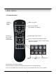
• Description 3. Remote Controller MENU: Open Menu POWER: System On/Off Channel Select Button (4ch Available, #1~4 Button) RETURN: ENTER: Apply Setup Change Cancel Setup or Return to Previous Menu Search Controller: Control Playback Option (EX. Speed of Playback, Move on Menu, Control PTZ/Focus, Volume) Change Screen Open Search Mode Mode PTZ/IRIS Mode • Unused Button's Description is Omitted. • Remote Controller can Operate when Remote Controller Sensor Input Part Reacted.
• Installation 1. 8pin RJ 45 Modular Jack Camera in (BNC/RCA/DIN)+ Audio in (RCA/DIN) + Power + RS-485 •Default : Camera (BNC) + Audio (RCA) •Optional Cable Selection (refer to page. 48 ) 2. Video Out Connect DC Power Input Terminal and Static Adaptor 3. Camera Selection Switch to change video mode NTSC/PAL 4. Network Connection Connect Ethernet Terminal and Network Cable ① 5.
• Installation ※ Hard Disk Format - If you install the unformat Hard Disk, System can’t recognize the Hard Disk. Please install the format Hard Disk.
• Display 1. System Power ON • Press Power Button once to turn on system • After Checking Hard Disk, Input password to operate.
• Display 3. Convert Screen Mode (SCR MODE) • User can Select 3 Kinds Watch Mode ① Quad (4CH) Division Watch Mode ② Selected 1CH Watch Mode ③ 4CH Rotation Watch Mode • Quad (4CH) Watch Mode is Initial Mode when System Start Quad (4CH) Division Watch Mode Selected 1CH Watch Mode 4CH Rotation Mode 4.
• Display 5. Speaker Volume Control • Easy to control speaker output volume monitoring “Live & Recorded image” 5. System Power OFF • Press Power Button to turn on monitor. • Press Power Button More than 3 seconds to see “shutdown popup window.
• SEARCH ⊙ Go to Search Mode SEARCH • Press Search Button and Log-In Administrator or Manager • Use Direction Key to Move Menu • To Open Each Menu Press Enter ENTER Search Recorded Data RETURN • Return to Previous. (Move to Previous Menu or Exit Search 1 Mode and Return to Watch Mode) 1.
• SEARCH • Control Playing Video ① : Normal Playing Mode (Normal Speed (1X) Forward Playing) ② : Normal Speed Backward Playing ③ : Pause Video ④ : Fast Forward (2 ~ 64 Speed) ⑤ : Fast Backward (2 ~ 64 Speed) ⑥ : Audio Volume Control ※ Press Normal Forward/Backward Button in Pause, Move to Next/Previous Frame. 2.
• SEARCH • Date : Indicate Event Occurrence Order & Date Time : Indicate Event Occurrence Time Event : Indicate Event Contents & Camera No. • Event Searching Method ① User can Search Event Using Direction key ② Search Event to Press Enter at Selected Event from Event Occurrence Time ③ Control Video is the same way as Time Mode Control Tip • The Search by Event is not Based on Video, but Event Occurrence Time.
• MENU ⊙ Go to Menu ① Press Menu Button on Front Panel in Watch Mode ② Ask Password ③ Input Password Using by Channel Select Button [1][2][3][4]) ④ After Input Password Press Enter to See Menu Tip • Initial Password for all “Administrator, User, Network” is 1234. • Showing Password as * • Changing Password (MENU->6.System->4.Password ) • Only Watch Mode can go to Menu.
• MENU 1.Display - Video Setup for Watch Mode 1. Date/Time : Date & Time Mark On/Off 2. Title : Camera Name On/Off 3. Status : Record Condition Mark On/Off (Recording: Red, Pre-recording : Green) 4. Border : Border Mark On/Off when 4CH Division Watch Mode 5. Border Color : Select Border Color (White, Blue, Red, Yellow, Green, Gray) 6. Sequence Dwell : Setup Rotation Cycle Time (1~60 Sec.) when 4CH Rotation Mode at Watch Mode 7. Spot-Out Dwell : Setup Spot-Out Time Cycle (1~60 Sec.
• MENU • Size : 352*240, 720*240, 720*480 Rec.Rate : Possible to Select (1~30) Quality : Possible to Select 3 levels (Highest, High, Low, Standard) • Indicate Frame No. to Control Size & Rec. Rate Overlimit Recording Capacity Tip • If Frame Over, Showing a Message ‘Overlimit Recording Capacity’ and Impossible to Change Size & Rec.
• MENU 2.3 Motion Detection Setup – Motion Detection Area & Sensitivity • Camera : Indicate Camera No. to Setup • Sensitivity : Control Sensitivity (1~100) Large No. is More Sensitive. • Region : Setup Motion Detect Range Entirely – Select Entire Screen Partially – Select Partial Screen • When Choose Region as Partially, Move to Partial Range Setup. Press Enter After Partial Range Setup to Finish Region Setup. • Pre-Motion Duration : Setup Pre-Motion Duration Time.
• MENU ⊙ Time Recording Weekly Setup ① ② Weekly mode Setup at Record Setup Scheduled Region Indicated Yellow ③ ④ After ‘Deselect’ Schedule, Activated Region by Press ‘ENTER’ and Select Date & Time to Move Cursor After Selecting Region and Press ‘ENTER’ Again to Finish Schedule Setup (Red) ⑤ ⑥ • Select All : Entire Region Select • Deselect All : Cancel Region • Save&Exit : Save Changing Setup & Exit • Cancel : Cancel Changing Setup & Exit Setup Date & Time Schedule in the Same Way.
• MENU ⊙ Partial Motion Region Setup :Non-Activate Move Cursor ① :Activate Partial Setup Cursor :Partial Setup Finish Cursor ② Region Initial View ④ When Select Multi Region, Using Direction Key in ② to Expand Non-Activate Region ⑦ :Non-Activated Region ③ Move Cursor by Direction Key and Press Enter at Selected Region ⑤ Press Enter again to see Region as a Blue Color and Setup NonActivate Region ⑥ Press Enter to Select Multi Non-Activate Region Same Method as ④⑤, Possible to Expand Non-Activ
• MENU 3.Camera - Setup Camera 3.1 Status/Title Setup – Camera Connection Status & Camera Name Setup • Camera : Indicate Camera No. to Setup • Status : Indicate Camera Status (Connected/Disconnected) • Title : Setup Camera Name to Show Left-Upper Side Tip • Title Input Method Using Direction Key, Up & Down Keys for Alphabet A~Z, Numerical No. 0~9 Left-Right Keys for Move to another Letter. 3.2 Covert/PTZ Setup • Camera : Indicate Camera No.
• MENU 3.3 Color Setup – Control Video Color • Camera : Indicate Camera No. to Setup • Brightness : Control Monitor Bright • Contrast : Control Monitor Contrast • Color : Control Monitor Color • Tint : Control Monitor Tint * All Setup Possible to Control 0~100 4.Audio - Setup Audio 4.1 Audio Recording Setup – Audio In Setup • Camera : Indicate Camera No. for Setup • Audio Rec. : Setup Recording On/Off from External Audio In Terminal • Audio Ch.
• MENU 4.2 Live Audio Setup – Audio Out Setup • Live Audio : Audio Output ON/OFF Live Audio Output from Audio In Terminal • Monitoring Ch. : Select Channel for Audio Output Nr. 1~4 Audio In 5.Alarm - Setup Alarm & Relay 5.1 Alarm Input Setup – Alarm Sensor Setup • Alarm : Indicate Alarm Input Terminal No. • Status : Setup Alarm Sensor Connection Status (Connected/Disconnected) • Camera : Input Camera No.
• MENU 5.2 Relay Output Setup – Alarm Relay Setup • Alarm : Indicate Alarm Input Terminal No. • Relay Out : Setup Relay Connect with Alarm Sensor • Mode : Setup Reacted Relay as Latched/Transparent Mode • Duration : Setup Reacted Relay Time (5sec~5min or Until key-in) • Relay Type : Setup Relay Type N/Open or N/Close Tip • Latched/Transparent Latched – When Sensor Alarm Activated, Relay Reacted in Setup Duration Transparent – Relay Reacted Temporary During Sensor Alarm Activate 6.
• MENU 6.2 Network – Setup TCP/IP • IP Address : Input IP Address • Gateway : Input Gateway IP for Internet Server • Subnet Mask : Input Subnet Mask IP • Network Speed : Setup Network Speed (Network Speed from System, Depend on Network Status) ※ When you the changed setting would be applied after rebooting You should reboot to apply changed setup change 6.
• MENU 6.4.2 Manager Password – Available to monitor & search but cannot change setup • Current Password : Input Current Password (Initial Password : 1234) • New Password : Input New Password • Re-enter the Password : Re-Confirm New Password • Save&Exit : Applying New Password 6.4.
• MENU 6.5 Disk Write Mode – Setup Hard Disk • Disk Overwrite : Select Overwrite Permission when Hard Disk Full O N: Overwrite Hard Disk from Oldest Data OFF: When Hard Disk Full, Stop Recording and Buzzer Activate (Refer to Menu 6.3 Buzzer Setup) • Disk Initialize Now : Refreshment Hard Disk All Recorded Data Deleted • When Select Disk Initialize, Alarm Message Showing. Select ‘Yes’ to Start Disk Initialize. ※When Change Disk Overwrite ON/OFF Mode, the Change will be Applied from Changing Time.
• MENU 7. USB BACK UP • USB device auto detection • Back up date & time • Selectable subject : Video/ Audio/ Event • You can back up data by USB device auto detection. • Set data and time which you want to back up and then press back up button • Back up will be started • You can select “Channel”, “Audio” & “event” which you want to back up.
• CLIENT • System Requirement ① Main Board (CPU): Celeron 500-700(Minimum), Pentium 4 recommend ② OS: More than Windows 98,DirectX 7.0A ③ Memory (RAM): More than 128 M ④ VGA: Overlay YV12 Format Graphic Card All Radeon, Nvidia (Above Geforce) Matrox (Above G400) Compatible Video Card ※ Above DIVX Codec 5.1 (When Use Media Player) • DVR Remote Agent 1.0 Install ① Open CD-ROM Drive and Run DvrRemoteAgentSetup.
• CLIENT ③ Ask designate Folder to Install DvrRemoteAgent 1.0, Recommend Basic setup c:\program files:\DvrRemote Agent 1.0 Click Next ④ Showing Progress of Copy of Files ⑤ Appear DirectX 7.0a Install Menu. If DirectX Version Lower than 7.
• CLIENT ⑥ When Finishing Installation, System must be Restarted. Click ‘Yes’ ⑦ Finish DvrRemoteAgent 1.
• CLIENT 1. Monitoring Mode ③ 1.1 Function Introduction ① ④ ⑤ ⑥ ⑦ ⑧ ⑨ ⑩ ⑪ ② ⑫ ① Main Screen Image : Shows Present Surveillance Camera Image ② Camera Selection Button : Indicates Connected Camera No. & Select Image to Click Camera No.
• CLIENT 1.2 Screen Division Selection • 1*1 View : Showing One (1) Video which User Selected (Selection Video by Camera Selection Button) • 4*4 View : Quad Screen Division Mode • Scenario View : One Large Screen Mode Showing One by One (1*1 View) Depend on User Selection Time (Not Work Screen Division Mode) • Full Screen View : Present Video Move to Full Screen Mode Mouse Double Click to Return Previous move *Mouse Double Click Make the Same Function as Full Screen. 1.
• CLIENT 1.5 AVI File Conversion • Click AVI Conversion Button to Start AVI File Conversion • During AVI Conversion Showing a Message and before Click ‘Stop”, Save AVI File continuously • Press ‘Stop’ to Open Designated File Name & Saving Location, and Save AVI File • Saved AVI File can Open Ordinary Moving Picture Player • Moving Picture Player Codec Version is Above Divx 5.1. 1.
• CLIENT 2.Search Mode 2.
• CLIENT 2.2 Search Method ⑤ ① ② ⑥ ④ ③ ① Indicate 0~24 Hour ② Indicate Recording Situation (Gray : No Record, Green : Recorded Image at the Time) ③ Search Bar : Select Video by Dragging Mouse Search Controller in Recorded Area ④ Indicate Camera Channel to Confirm Camera Recording Situation ⑤ Refreshment Recording Information Situation Window by Camera Channel ⑥ If Connected Channel is more than 5ch, Another Channel will be Scrolled.
• CLIENT 2.3 SEARCH Option ⑤Log Search ⑥Event Viewer ①Backup ②Backup Play ④Print Image ③Save Image ① Backup – Backup Image from Server to Remote PC • Backup Time : Designate Backup Time (Now or Later) • Designate Backup Date & Time when you chooseLater AM • Source : AM AM AM PM AM AM PM Designate Backup Image Data Length to Input Start Time & End Time. • Channel : Check Camera Channel for Backup • Select All Deselect All •Press OK to Open Backup Status & Start Backup.
• CLIENT ② Backup Play (DVR Player) – Transfer to DVR Player ① ② ③ ④ ⑤ ① Showing Image (Possible to Only 1*1View Mode) ② Backup File Open to Play First Video Ex. : ch04_10261450_10261455.rec ( Backup File for # 4 ch. October.26, 14:50 ~14:55 ) ③ Indicate Total Recorded time of Present Playing Picture.
• CLIENT ③ Save Image – Capture Image & Saving Image at Hard Disk or Removable Disk • Click ‘Save Image’ Icon During Playing Video • Designate File name, File Type (JPG,BMP), and Location and Press Saving • Conversion and Saving Image from Remote Viewer ③ Print Image – Present Image Capture and Print Out Image • During Play Video, Click ‘Print Image’ • After Selecting Printer, Start Image Printing • Print Out Remote Viewer Image 42
• CLIENT ③ Log Search – Find Video Centering around Event Log at Server ① ② ③ ④ ⑤ ⑥ ⑧ ⑦ ① Input Start Time and End Time at the Selected Date to Search Event When Press Search Button, Event Output at the Below Window ② Indicate Event Log Order No. ( Max Event Log No. of 1 Page is 100 ) ③ Indicate Event Occurred Camera No.
• CLIENT ④ Event Viewer – Showing Present Event in Server & Find Image ① Indicate Event Occurred Order No. ② Indicate Event Occurred Camera No.
• CLIENT 3.Setting ① ① ② ② ⑦ ③ ⑧ ④ ⑨ ⑤ ⑩ ⑥ 3.1 Connection ID Setup ① ID Status : Indicate Present Saving ID & ID Information ② Input Name to Add or Amend ID ③ Input IP Address to Add or Amend Server ④ Indicate Port No.
• CLIENT 3.2 Option Setting ① Control Screen Rotation Time in Scenario Mode at Watch Mode (Possible to Setup from 1~300 sec.) ② Possible to Select Event Kind Plurally from Server. Remote Client Only can See Selected Event.
• DDNS Connection 1. Setting Domain Name Connection When you have finished DDNS network setup and reboot, 1. Check the MAC address in “System Information” menu. 2. The domain name is "MAC address.dvrlink.net”. EX) If Mac Address is 00-11-5f-01-0a-7a, the domain name is "00115f010a7a.dvrlink.net" 3. You can connect by "00115f010a7a.dvrlink.net" on the remote agent program or Web browser. 1.
• OPTIONAL 1.