
Instruction manual


-7-
This appliance must be installed in accordance with the rules in force and used only in a
sufficiently ventilated space. Consult instructions before installation of this appliance.
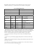
GAS SYSTEM INFORMATION
HEAT INPUT 38.1 kW GROSS
GAS FLOW RATE 3.5 m
3
PER HOUR
BURNER PRESSURE 8.7 mbar G20 / 12.2 mbar G25
INJECTOR SIZE 3.9 mm
COUNTRY CATEGORY ORIFICE (mm)
2
ND
/ 3
RD
FAMILY
REGULATOR. SETTING mBAR
2
ND
/ 3
RD
FAMILY
GB IE IT CH
ES
II 2H3+ 3.9 / 2.4 8.7 / ANNULLED
FR II
Er3+(29/37)
3.9 / 2.4 8.7 (G20),12.2 (G25) /
ANNULLED
BE I 2E(S)B 3.9 / NA 8.7 (G20),12.2 (G25) / NA
DE II 2EB/P 3.9 / 2.4 8.7 / 22.4
NL II 2L3B/P(50) 3.9 / 2.4 12.2 / 22.4
DK GR II 2H3B/P 3.9 / 2.4 8.7 / 22.4
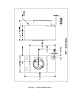
The inlet gas connection to the unit is ISO 7-RC 3/4 thread. The connection to the appliance
shall be made with a flexible hose suitable for the appliance category in accordance with national
installation regulations. The size of the piping to supply the dryer should be determined by
reference to national installation practice and consultation with the local gas supplier.
A joint compound resistant to all fuel gases must be employed in making threaded pipe
connections.
A drip tee is to be provided in the gas piping entering the unit to catch dirt and other foreign
articles.
All pipe connections should be checked for leakage with a suitable leak detection fluid. Never
check with an open flame.
Note: There are two 9 mm pressure taps, one at the inlet side, one at the outlet side of the gas
valve, for use if it is necessary to check either pressure.