CB64-BX/ZX Rev.
Copyright This publication contains information that is protected by copyright. No part of it may be reproduced in any form or by any means or used to make any transformation/ adaptation without the prior written permission from the copyright holders. This publication is provided for informational purposes only.
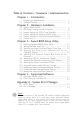
Table of Contents / Sommaire / Inhaltsverzeichnis Chapter 1 - Introduction 1.1 Features and Specifications ................................................................. 1.2 Package Checklist ...................................................................................... Chapter 2 - Hardware Installation 2.1 2.2 2.3 2.4 2.5 2.6 System Board Layout ............................................................................. DIP Switch Settings of the Processors ..................................
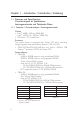
Chapter 1 - Introduction / Introduction / Einleitung 1.1 Features and Specifications Caractéristiques et Spécifications Leistungsmerkmale und Technische Daten 1.1.1 Features / Caractéristiques / Leistungsmerkmale Chipset Intel 440BX AGPset (CB64-BX) Intel 440ZX-100 AGPset (CB64-ZX) ESS Solo-1 PCI AudioDrive Processor The system board is equipped with Socket 370 and a switching voltage regulator that automatically detects 1.30V to 2.05V.
Introduction Expansion Slots The system board is equipped with 1 dedicated AGP slot, 4 dedicated PCI slots, 2 dedicated 16-bit ISA slot. All PCI and ISA slots are bus masters except PCI4 in the CB64-ZX which is slave only.
1 Introduction Bus mastering reduces CPU utilization during disk transfer ATAPI CD-ROM, LS-120 and ZIP supported IrDA Interface The system board is equipped with an IrDA connector for wireless connectivity between your computer and peripheral devices. It supports peripheral devices that meet the IrDA or ASKIR standard. USB Ports The system board is equipped with two USB ports.
Introduction Wake-On-Keyboard/Wake-On-Mouse This function allows you to use the keyboard or mouse to poweron the system. Refer to sections 2.5 (chapter 2) and 3.10 (chapter 3) for more information. Important: The power button will not function once a keyboard password has been set in the KB Power On Password field of the Integrated Peripherals setup. You must type the correct password to power-on the system. The 5VSB power source of your power supply must support ≥720mA (minimum).
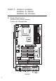
Chapter 2 - Hardware Installation Installation du Matériel Installation der Hardware 2.
Hardware Installation 2 CB64-ZX Note: The illustrations on the following pages are based on the CB64-BX system board, which is the board equipped with three DIMM sockets.
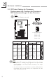
2 Hardware Installation 2.2 DIP Switch Settings for Processors Positionnement des Cavaliers des Processeurs DIP Schaltereinstellungen für den Prozessor Note: SW1 is for factory use only. In the example above: Switch Switch Switch Switch Processor Processor 66MHz 100MHz Frequency Ratio 4.5x 433MHz Future processor 6.5x Future processor 5x 466MHz Future processor 7x 366MHz Future processor 5.5x Future processor Future processor 7.
Hardware Installation 2 2.3 Jumper Settings for the CPUs Front Side Bus Positionnement des Cavaliers pour le Bus Frontal du Processeur Jumpereinstellungen fuer CPU Vorderseitenbus Jumper JP2 - CPUs Front Side Bus Select The default setting of jumper JP2 is Auto - the system will automatically run according to the FSB of the processor. The 100MHz setting (12-3 Off) is reser ved for future 100MHz FSB processors. Refer to the figure below.
2 Hardware Installation 2.4 Jumper Settings for Clearing CMOS Data Positionnement des Cavaliers pour Effacer les Données CMOS Jumpereinstellungen zum Löschen der CMOS Daten Jumper JP3 - CMOS Clear To load the default values stored in the ROM BIOS, please follow the steps below. 1. Power-off the system and unplug the power cord. 2. Set JP3 pins 2 and 3 to On. Wait for a few seconds and set JP3 back to its default setting, pins 1 and 2 On. 3. Plug the power cord and poweron the system.
Hardware Installation 2 2.5 Jumper Settings for Wake-On-Keyboard/Mouse Positionnement des Cavaliers pour Réveil-Sur-Clavier/ Souris Jumpereinstellungen für die Wake-On Tastatur/Maus Jumper JP1 - Wake-on-Keyboard/Mouse To use the keyboard or mouse to power-on the system, please follow the steps below. 1. Set JP1 to 2-3 On, enable. 2. Keyboard/Mouse Power On in the Integrated Peripherals setup of the Award BIOS must be set accordingly. Refer to section 3.10 (chapter 3) for more information.
2 Hardware Installation 2.6 Connectors / Connecteurs / Anschlüsse 2.6.1 Floppy Disk Drive Controller and IDE Interface Contrôleur de Lecteur de Disquette et Interface IDE Diskettenlaufwerkcontroller und IDE Interface Important: If you encountered problems while using an ATAPI CD-ROM drive that is set in Master mode, please set the CD-ROM drive to Slave mode. Some ATAPI CD-ROMs may not be recognized and cannot be used if incorrectly set in Master mode. 2.6.
Hardware Installation 2 2.6.3 CPU Fan Connector Connecteur du Ventilateur de CPU CPU Kühlung Anschluß Pin Function 1 On/Off 2 +12V 3 Sense 2.6.
2 Hardware Installation 2.6.5 AGP Fan Connector Connecteur de Ventilateur AGP Anschluß AGP Kühlung Pin Function 1 Ground 2 +12V 3 N. C. 2.6.
Hardware Installation 2 Connect the CD audio cable to J23 (Mitsumi CD-ROM) or J22 (Sony CD-ROM) if the audio cable included in your CD-ROM package should look somewhat similar to the one on the right. Connect the CD audio cable to J21 (Sony CD-ROM) if the audio cable included in your CD-ROM package should look somewhat similar to the one on the right. 2.6.
2 Hardware Installation 2.6.
Hardware Installation HD-LED (Primary/Secondar y IDE LED) G-LED (Green LED) ATX-SW (ATX power switch) G-SW (Green switch) RESET (Reset switch) SPEAKER (Speaker connector) KEYLOCK (Keylock and Power LED connector) Pin 1 2 3 4 5 6 7 8 9 10 11 12 13 14 15 16 17 18 19 20 21 22 23 24 25 2 Pin Assignment HDD LED Power HDD N. C. Green LED Power Green N. C. PWRBT Ground N. C. SMI Ground N. C. H/W Reset Ground N. C. Speaker Data N. C. Ground Speaker Power N. C. LED Power N. C.
2 Hardware Installation 2.6.9 Power Connector Connecteur dAlimentation Netzanschluß PS1 connectors pin assignment. Pin Function Pin Function 1 3.3V/14A 11 3.3V/14A 2 3.3V/14A 12 -12V 3 COM 13 COM 4 +5V 14 PS-ON 5 COM 15 COM 6 +5V 16 COM 7 COM 17 COM 8 PW-OK 18 -5V 9 5VSB 19 +5V 10 +12V 20 +5V Important: Your power supply must meet the ATX specification - supporting 3.3V/14A (minimum), otherwise your system will not boot properly.
Chapter 3 - Award BIOS Setup Utility Utilitaire de Configuration du Award BIOS AWARD BIOS Konfigurationsprogramm 3.1 Entering the Award BIOS Setup Utility Entrer Dans lUtilitaire de Configuration du Award BIOS Aufruf des AWARD BIOS Konfigurationsprogramms Power-on the system and press to enter the utility. The main program screen will appear. Allumez le Système et appuyez sur pour entrer dans lutilitaire. Lécran du programme principal apparaîtra.
3 Award BIOS Setup Utility 3.2 Setting the Date and Time Paramétrage de la Date et de lHeure Einstellen des Datums und der Zeit ROM PCI/ISA BIOS STANDARD CMOS SETUP AWARD SOFTWARE, INC. Date (mm:dd:yy) : Fri, Mar 5 1999 Time (hh:mm:ss) : 13: 27: 50 HARD DISKS Primary Master : Primary Slave : Secondary Master : Secondary Slave : TYPE SIZE CYLS HEAD Auto 0 0 0 Auto 0 0 0 Auto 0 0 0 Auto 0 0 0 PRECOMP LANDZ SECTOR MODE 0 0 0 Auto 0 0 0 Auto 0 0 0 Auto 0 0 0 Auto Drive A : 1.44M, 3.5 in.
Award BIOS Setup Utility 3 3.3 Selecting the Hard Drive and Floppy Drive Type Sélectionnez le Type de Disque Dur et de Lecteur de Disquette Auswahl der Festplatte und des Diskettenlaufwerks ROM PCI/ISA BIOS STANDARD CMOS SETUP AWARD SOFTWARE, INC.
3 Award BIOS Setup Utility 3. Set the type of floppy drive installed in the Drive A and Drive B fields. The options are None, 360K, 1.2M, 720K, 1.44M and 2.88M. Paramétrez le type de lecteur de disquette installé dans les champs Drive A et Drive B. Les options sont None, 360K, 1.2M, 720K, 1.44M et 2.88M. Im Eintrag Floppy Drive (Diskettenlaufwerk) wählen Sie Drive A (Laufwerk A) und Drive B (Laufwerk B). Die Optionen sind None (Kein), 360K, 1.2M, 720K, 1.44M und 2.88M. 3.
Award BIOS Setup Utility 3 Sélectionnez le lecteur qui devra être détecté en premier dans le champs Boot Sequence. La valeur par défaut est A, C, SCSI. Les autres options sont: C, A, SCSI; C, CDROM, A; CDROM, C, A; D, A, SCSI; E, A, SCSI; F, A, SCSI; SCSI, A, C; SCSI, C , A; C seulement et LS/ZIP, C. Im Boot Sequence Feld wählen Sie die Sequenz, in welcher der Computer nach einem Betriebssystem sucht.
3 Award BIOS Setup Utility 1. Select Chipset Features Setup in the main program screen and press . Sélectionnez Chipset Features Setup dans lécran de programme principal et appuyez sur . Chipset Features Setup in dem Hauptbildschirm auswählen, und die Eingabetaste (Enter) drücken. 2. Select the external system bus clock of your processor in the CPU/PCI Clock (MHz) field. The options are Default, 66.8/33.4, 75/37.5, 83.3/41.65, 100.3/33.4, 103/34.33, 105/35, 110/36.67, 112/37.
Award BIOS Setup Utility 3 Sélectionnez lHorloge Externe de Bus Système de votre processeur dans le champ CPU/PCI Clock (MHz). Les options par Default, 66.8/33.4, 75/37.5, 83.3/41.65, 100.3/33.4, 103/ 34.33, 105/35, 110/36.67, 112/37.33, 115/38.33, 120/40, 124/ 31, 124/41.33, 133/33.25, 133/44.33, 140/35 et 150/37.5. Lhorloge PCI apparaîtra simultanément à côté de lhorloge bus externe en sélectionnant lhor loge bus externe de votre processeur. Si, par exemple, on sélectionne 66.8/33.
3 Award BIOS Setup Utility Im CPU/PCI Clock (MHz) Feld sind folgende. Sind die Optionen Default, 66.8/33.4, 75/37.5, 83.3/41.65, 100.3/33.4, 103/34.33, 105/35, 110/36.67, 112/37.33, 115/38.33, 120/40, 124/31, 124/41.33, 133/33.25, 133/44.33, 140/35 und 150/ 37.5. Beim Auswählen des externen Bus-Taktgeber s Ihres Prozessors erscheint der PCI-Taktgeber gleichzeitig neben dem ausgewählten externen Bus-Taktgeber. Wählen Sie beispielsweise 66.8/33.4 aus, beträgt der externe Bus-Taktgeber 66.
Award BIOS Setup Utility 3 3.6 Selecting an IRQ for the External Modem Sélectionner une IRQ pour le Modem Externe IRQ Bestimmung für ein externes Modem ROM PCI/ISA BIOS POWER MANAGEMENT SETUP AWARD SOFTWARE, INC.
3 Award BIOS Setup Utility 3.7 Selecting the Method of Powering-off the System Sélection de la Méthode pour Eteindre le Système Auswahl der Abschaltmethode ROM PCI/ISA BIOS POWER MANAGEMENT SETUP AWARD SOFTWARE, INC.
Award BIOS Setup Utility 3 Si le bouton de mise sous tension est poussé puis relâché en moins de 4 secondes, le système entrera en mode suspend. Poussez le et relâchez le à nouveau en moins de 4 secondes pour restaurer la fonction. Le fait dappuyer sur le bouton de mise sous tension pendant plus de 4 secondes éteindra le système. Wird die Netztaste gedrückt und innerhalb von 4 Sekunden wieder losgelassen, schaltet sich das System in den Suspend-Modus.
3 Award BIOS Setup Utility 1. Select Power Management Setup in the main program screen and press . Sélectionnez Power Management Setup dans lécran de programme principal et appuyez sur . Power Management Setup in dem Hauptbildschirm auswählen, und die Eingabetaste (Enter) drücken. 2. Select the PWR Lost Resume State field. The options are: Sélectionnez PWR Lost Resume State. Les options sont In dem Feld PWR Lost Resume State.
Award BIOS Setup Utility 3 où vous lavez laissé avant la coupure dalimentation. Si le système est éteint quand la coupure dalimentation CA se produit, il restera éteint lorsque le courant sera rétabli. Si le système est allumé quand la coupure dalimentation se produit, le système sallumera lorsque le courant sera rétabli. Beim Wiederherstellen der Stromversorgung nach einem Wechselstromausfall kehr t das System in den Status zurück, in welchem es sich beim Auftreten des Stromausfalles befand.
3 Award BIOS Setup Utility Chipset Features Setup in dem Hauptbildschirm auswählen, und die Eingabetaste (Enter) drücken. 2. System Health Monitor Current System Temperature, Current CPU Temperature, Current Chassis Fan Speed and Current CPU Fan Speed These fields show the internal temperature of the system, current temperature of the processor, and the current fan speed of the chassis and CPU fans in RPM (Revolutions Per Minute).
Award BIOS Setup Utility 3 utilitaire est inclus dans le CD fourni. Pour plus de renseignements , reportez-vous à Hardware Doctor Utilitaires chapitre 4 de ce manuel. Soll ein akustisches Signal ertönen und erscheint ein Warnhinweis wird abnormaler Zustand festgestellt, muß das Hardware-Doctor-Dienstprogramm installiert werden, das Sie auf der mitgelieferten CD finden. Sie unter Hardware Doctor Hilfsprogramme in Kapitel 4 dieses Handbuches nach, um weitere Information zu erhalten. 3.
3 Award BIOS Setup Utility Disabled Default setting / Valeur par défaut / Voreinstellung. Warning / Attention / Warnung: If JP1 was previously enabled with a password set in the KB Power On Password field, and now you wish to disable the Wake-OnKeyboard (password) function, make sure to set this field to disabled prior to setting JP1 to disabled (1-2 On). You will not be able to boot up the system if you fail to do so.
Award BIOS Setup Utility 3 bis zu 5 Zeichen eingeben. Tippen Sie nocheinmal genau dasselbe Passwor t ein, um dieses zu bestaetigen und druecken Sie dann . Important / Important / Wichtig: The power button will not function once a keyboard password has been set in the KB Power On Password field. You must type the correct password to power-on the system. Le bouton de mise sous tension ne fonctionnera plus une fois quun mot de passe aura été entré dans le champ KB Power On Password.
3 Award BIOS Setup Utility Wenn diese Option gewaehlt wird, druecken Sie zweimal die linke Maustaste, um das System zu starten. Mouse Right When this option is selected, double-click the right button of the mouse to power-on the system. Quand cette option est choisie, double-cliquez sur le bouton droit de la souris pour allumer le système. Wenn diese Option gewaehlt wird, druecken Sie zweimal die rechte Maustaste, um das System zu starten. Any Key You can press any key to power-on the system.
Award BIOS Setup Utility 3 3.11 Loading Fail-Safe Settings/Optimal Settings Charger les Paramètres à Sécurité Relative Optimaux Laden der Fail - Safe Einstellungen / Optimierte Einstellungen The Load Fail-Safe Settings option loads the troubleshooting default values permanently stored in the ROM chips. These settings are not optimal and turn off all high performance features. You should use these values only if you have hardware problems.
3 Award BIOS Setup Utility Définir le Mot de Passe Superviseur/Utilisateur Si vous désirez protéger votre système et Install contre toute entrée non autorisée, paramétrez un mot de passe dans le champ Supervisor Password. Si vous désirez protéger laccès à Install seulement, mais pas votre système, paramétrez un mot de passe dans le champ User Password. Utilisez les touches fléchées pour sélectionner le champ Supervisor Password ou User Password et appuyez sur .
Chapter 4 - Supported Softwares Logiciels Supportés Unterstützte Software 4.1 Hardware Doctor Utility Hardware Doctor Utilitaires Hardware Doctor Hilfsprogramme The system board comes with a Hardware Doctor utility contained in the provided CD. This utility is capable of monitoring the systems health conditions and allows you to manually set a range (Highest and Lowest Limit) to the items being monitored. If the settings/ values are over or under the set range, a warning message will popup.
4 Supported Softwares 4.2 Patch Utility for Windows 95 Patch Utilitaires Pour Windows 95 Patch Hilfsprogramme Zum Windows 95 The CD included in the system board package contains a patch utility. If you are r unning Windows 95 (Win95, Win95+, Win95 OSR1: Windows 95 OEM Service Release 1, Win95 OSR2: Windows 95 OEM Service Release 2.0 or Win95 OSR2.1: Windows 95 OEM Service Release 2.0 plus USB Supplement), you need to run the patch utility.
Appendix A - System Error Message Messages dErreur du Système Fehlernachricht des Systems When the BIOS encounters an error that requires the user to correct something, either a beep code will sound or a message will be displayed in a box in the middle of the screen and the message, PRESS F1 TO CONTINUE, CTRL-ALT-ESC or DEL TO ENTER SETUP, will be shown in the information box at the bottom. Enter Setup to correct the error. A.
A System Error Message setting than indicated in Setup. Determine which setting is correct, either turn off the system and change the jumper or enter Setup and change the VIDEO selection. FLOPPY DISK(S) fail (80) Unable to reset floppy subsystem. FLOPPY DISK(S) fail (40) Floppy type mismatch. Hard Disk(s) fail (80) HDD reset failed. Hard Disk(s) fail (40) HDD controller diagnostics failed. Hard Disk(s) fail (20) HDD initialization error. Hard Disk(s) fail (10) Unable to recalibrate fixed disk.