NB32-SC NB32-SL Rev.
Copyright This publication contains information that is protected by copyright. No part of it may be reproduced in any form or by any means or used to make any transformation/adaptation without the prior written permission from the copyright holders. This publication is provided for informational purposes only.
Battery: Danger of explosion if battery incorrectly replaced. Replace only with the same or equivalent type recommend by the manufacturer. Dispose of used batteries according to the batter y manufacturers instructions. Joystick or MIDI port: Do not use any joystick or MIDI device that requires more than 10A current at 5V DC . There is a risk of fire for devices that exceed this limit.
Quick Setup Guide Quick Setup Guide Table of Contents Chapter 1 Quick Setup Guide............................................. 5 Chapter 2 English...................................................................... 25 Chapter 3 Français (French)................................................. 42 Chapter 4 Deutsch (German)................................................ 59 Chapter 5 Español (Spanish)..................................................
Chapter 1 - Quick Setup Guide Table of Contents 1.1 System Board Layout.................................................................................................. 6 1.2 Jumpers..................................................................................................................................... 8 1.3 Ports and Connectors................................................................................................ 10 1.4 Award BIOS Setup Utility...................................
Quick Setup Guide Quick Setup Guide 1.
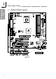
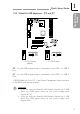
Quick Setup Guide Quick Setup Guide NB32-SL (Supports Onboard LAN) Note: The illustrations on the following pages are based on the NB32-SL system board, which is the board that supports onboard LAN.
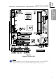
Quick Setup Guide Quick Setup Guide 1.2 Jumpers 1.2.1 Clear CMOS Data - JP4 1 2 3 1 2 3 1-2 On: Normal (default) 2-3 On: Clear CMOS Data 1.2.2 Wake-On-Keyboard / Wake-On-Mouse - JP1 1 2 3 1 2 3 1-2 On: Disable the Wake-OnKB/Mouse function (default) 2-3 On: Enable the Wake-OnKB/Mouse function Important: The 5VSB power source of your power supply must support ≥720mA.
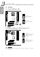
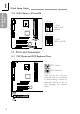
Quick Setup Guide 1 1 2 3 1 2 3 1 Quick Setup Guide 1.2.3 Wake-On-USB Keyboard - JP2 and JP7 2 3 2 3 JP7 JP2 1-2 On: Disable (default) JP7 JP2 2-3 On: Enable JP2 - for the USB keyboard that is connected to the USB 1 or USB 2 port. JP7 - for the USB keyboard that is connected to the USB 3 or USB 4 port. USB KB Wake-Up From S3 in the Power Management Setup submenu of the BIOS must also be enabled.
Quick Setup Guide Quick Setup Guide 1.2.4 USB 4 Select - JP5 and JP6 JP5 JP6 1 2 3 1-2 On: USB 4 on J8 (default) JP5 JP6 1 2 3 2-3 On: USB 4 on CNR 1.3 Ports and Connectors 1.3.1 PS/2 Mouse and PS/2 Keyboard Ports PS/2 Mouse PS/2 Keyboard Make sure to turn off your computer prior to connecting or disconnecting a mouse or keyboard. Failure to do so may damage the system board.
Quick Setup Guide Quick Setup Guide 1.3.2 RJ45 Fast-Ethernet Port (NB32-SL) RJ45 LAN 1.3.3 Universal Serial Bus Ports Onboard USB Ports (USB 1 / 2) Additional USB Ports (USB 3 / 4) 1 2 3 4 5 6 7 8 VCC UP2UP2+ Ground Key VCC UP3UP3+ 9 10 11 12 13 14 15 Ground Ground Ground Ground UP2+ UP2VCC The Wake-On-USB Keyboard function, when enabled, allows a USB keyboard to wake up a system that is in the S3 (STR Suspend To RAM) state.
Quick Setup Guide Quick Setup Guide 1.3.4 Parallel Port Parallel Por t 1.3.
1.3.6 Game/MIDI Port and Audio Jacks Onboard Game/MIDI / Audio Game/MIDI Port Audio Jacks Quick Setup Guide Quick Setup Guide Line-out Line-in Mic-in Additional Line-out/Mic-in (J2) 1 2 3 4 5 6 7 8 9 10 Mic+ Ground N. C. AuD_Vcc (Avcc) AuD_R-Out N. C. N. C. Key AuD_L_Out N. C. 1.3.
Quick Setup Guide Quick Setup Guide 1.3.8 Chassis Open Connector 1 2 3 4 Ground Chassis signal N. C. +5V 1.3.9 Floppy and IDE Disk Drive Connectors FDD IDE If you encountered problems while using an ATAPI CD-ROM drive that is set in Master mode, please set the CD-ROM drive to Slave mode. Some ATAPI CD-ROMs may not be recognized and cannot be used if incorrectly set in Master mode.
1.3.10 IrDA Connector 1 2 3 4 5 VCC N. C. IRRX Ground IRTX Quick Setup Guide Quick Setup Guide The sequence of the pin functions on some IrDA cable may be reversed from the pin function defined on the system board. Make sure to connect the cable to the IrDA connector according to their pin functions. 1.3.
Quick Setup Guide Quick Setup Guide 1.3.12 Wake-On-LAN Connector 1 WOL 2 Ground 3 +5VSB The 5VSB power source of your power supply must support ≥720mA. 1.3.13 Wake-On-Ring Connector 1 Ground 2 RI# If you are using a modem add-in card, the 5VSB power source of your power supply must support ≥720mA.
Quick Setup Guide Quick Setup Guide 1.3.14 DIMM and PCI Standby Power LEDs 3.3VSB Standby for PCI - Jumper JP3 1 2 On: Default 3.3VSB Standby Power to PCI slots - PCI 2.2 spec. 1 2 Off: Non-PCI 2.2 spec. DIMM Standby Power LED This LED will turn red when the systems power is on or when it is in the Suspend state (Power On Suspend or Suspend to RAM). It will not light when the system is in the Soft-Off state.
Quick Setup Guide Quick Setup Guide 1.3.15 Power Connector 1 2 3 4 5 6 7 8 9 10 ATX Main Power 1 1 3.3V 3.3V 1 2 -12V 3.3V 1 3 Ground Ground 1 4 PS-ON +5V 1 5 Ground Ground 1 6 Ground +5V 1 7 Ground Ground 1 8 -5V PW-OK 1 9 +5V 5VSB 2 0 +5V +12V +12V Power 1 Ground 2 Ground 3 +12V 4 +12V Auxiliary Power 4 +3.3V 1 Ground 5 +3.3V 2 Ground 6 +5V 3 Ground We recommend that you use a power supply that complies with the ATX12V Power Supply Design Guide Version 1.1.
Quick Setup Guide Quick Setup Guide 1.3.16 Front Panel Connectors Pin Pin Assignment HD-LED (Primary/Secondary IDE LED) G-LED (Green LED) 3 5 14 16 HDD LED Power HDD ATX-SW (ATX power switch) G-SW (Green switch) 8 10 18 20 RESET (Reset switch) SPEAKER (Speaker connector) 7 9 13 15 17 19 PWR-LED (Power/Standby LED) 2 4 6 Green LED Power Ground PWRBT+ PWRBTGround SMI Ground H/W Reset Speaker Data N. C.
Quick Setup Guide Quick Setup Guide 1.4 Award BIOS Setup Utility 1.4.
1.4.3 Advanced BIOS Features CMOS Setup Utility - Copyright (C) 1984-2000 Award Software Advanced BIOS Features BIOS Flash Protect Virus Warning CPU L1 & L2 Cache Quick Power On Self Test First Boot Device Second Boot Device Third Boot Device Boot Other Device Swap Floppy Drive Boot Up Floppy Seek Boot Up NumLock Status Typematic Rate Setting X Typematic Rate (Chars/Sec) X Typematic Delay (Msec) Security Option OS Select For DRAM > 64MB HDD S.M.A.R.T.
Quick Setup Guide Quick Setup Guide 1.4.
1.4.
Quick Setup Guide Quick Setup Guide 1.4.8 PC Health Status CMOS Setup Utility - Copyright (C) 1984-2000 Award Software PC Health Status Current System Temp. Current CPU Temperature Current System FAN Speed Current CPU FAN Speed Current Second FAN Speed CPU (V) : +3.3 V : +5 V : +12 V : -12 V : VBAT (V) : 5VSB (V) : 27C/80F 40C/66F 0 RPM 0 RPM 0 RPM 2.06 V 3.31 V 5.05 V 12.03 V -11.37 V 3.21 V 5.
English Chapter 2 - English 2.1 Features and Specifications..................................................................................... 26 2.2 Using the Suspend to RAM Function.......................................................... 33 2.3 Supported Softwares................................................................................................... 35 2.4 Troubleshooting................................................................................................................
English 2.1 Features and Specifications 2.1.1 Features Chipset English Intel® 845 chipset - Intel® 82845 Memory Controller Hub (MCH) - Intel® 82801BA I/O Controller Hub (ICH2) Processor The system board is equipped with Socket 478 for installing a Pentium® 4 processor. Intel® Pentium® 4 processor (478-pin) 400MHz system data bus Important: The frequency ratio of some processors may have been locked by the manufacturer.
English Expansion Slots The system board is equipped with 1 AGP slot, 2 dedicated PCI slots and 1 shared PCI/CNR slot. Pipelined memory read and write operations that hide memory access latency. Demultiplexing of address and data on the bus for nearly 100 percent efficiency. English The AGP slot only supports 1.5V AGP 4x (1066MB/sec. bandwidth) add-in cards. AGP is an interface designed to support high performance 3D graphics cards for 3D graphics applications.
English ATX Double Deck Ports (PC 99 color-coded connectors) English Two USB ports One RJ45 LAN (NB32-SL) Two NS16C550A-compatible DB-9 serial ports One SPP/ECP/EPP DB-25 parallel port One mini-DIN-6 PS/2 mouse port One mini-DIN-6 PS/2 keyboard port One game/MIDI port Three audio jacks: line-out, line-in and mic-in Connectors One connector for 2 additional external USB ports One connector for IrDA interface Two IDE connectors One floppy drive interface supports up to
English 3rd and 4th USB ports. These optional USB por ts, which are mounted on a card-edge bracket, will be provided as an option. USB allows data exchange between your computer and a wide range of simultaneously accessible external Plug and Play peripherals. Award BIOS, Windows® 98/2000/ME Plug and Play compatible Supports SCSI sequential boot-up Flash EPROM for easy BIOS upgrades Supports DMI 2.0 function Desktop Management Interface (DMI) The system board comes with a DMI 2.
English 2.1.3 Intelligence Automatic System/Second Fan Off The system and second fans will automatically turn off once the system enters the Suspend mode. English Dual Function Power Button Depending on the setting in the Soft-Off By PWR-BTTN field of the Power Management Setup, this switch will allow the system to enter the Soft-Off or Suspend mode.
English battery. Wait for a few seconds and install it back before powering-on the system. The 5VSB power source of your power supply must support ≥720mA. Wake-On-USB Keyboard Important: If you are using the Wake-On-USB Keyboard USB ports, the 5VSB power source of your must support ≥1.5A. If you are using the Wake-On-USB Keyboard USB ports, the 5VSB power source of your must support ≥2A.
English Important: The 5VSB power source of your power supply must support ≥1A. AC Power Failure Recovery English When power returns after an AC power failure, you may choose to either power-on the system manually, let the system power-on automatically or return to the state where you left off before power failure occurs. 32 Virus Protection Most viruses today destroy data stored in hard drives. The system board is designed to protect the boot sector and partition table of your hard disk drive.
English 2.2 Using the Suspend to RAM Function 1. Select Power Management Setup in the main menu screen and press . 2. In the ACPI Function field, select Enabled. 3. In the ACPI Suspend Type field, select S3(STR). 4. Press to return to the main menu. 5. Select Save & Exit Setup and press . Type and press . 6. Install Windows® 98 by typing the following parameter. This is to ensure that the ACPI function is supported.
English 11. Click the Advanced tab. In the When I press the power button on my computer field, select Standby. English 12. After completing the steps above and you want to power-off the computer, you do not need to go through the process of closing files, applications and operating system. You can poweroff the computer at once by pressing the power button or selecting Standby when you shut down Windows® 98. To power-on the computer, just press the power button.
English 2.3 Supported Softwares The system board comes with the Hardware Doctor utility contained in the provided CD. This utility is capable of monitoring the systems health conditions and allows you to manually set a range (Highest and Lowest Limit) to the items being monitored. If the settings/ values are over or under the set range, a warning message will popup. The utility can also be configured so that a beeping alarm will sound whenever an error occurs.
English 3. The Welcome screen will appear. Click Next. 4. The Software License Agreement screen will appear. Click Yes. 5. The Readme Information screen will appear. You can view the content of the utilitys readme in this screen. Click Next. 6. The Choose Destination Location screen will appear showing where the utility will be located. Click Next. English 7. The Actions screen will appear. Click Next to install the utility. 8. Restart the system. 9.
English 2.3.5 Microsoft DirectX 8.0 Driver 1. Insert the CD that came with the system board package into a CD-ROM drive. The autorun screen (Main Board Utility CD) will appear. 2. Click Microsoft DirectX 8.0 Driver. 3. Click Yes to continue. 5. Restart the system. 2.3.6 Drivers and Utilities Installation Notes English 4. Follow the prompts on the screen to complete installation. 1. "Autorun" ONLY supports the Windows 98, Windows 98 SE, Windows ME, Windows 2000 and Windows NT 4.
English 2.4 Troubleshooting This section of the manual is designed to help you with problems that you may encounter with your personal computer. To efficiently troubleshoot your system, treat each problem individually. This is to ensure an accurate diagnosis of the problem in case a problem has multiple causes. English Some of the most common things to check when you encounter problems while using your system are listed below. 1. The power switch of each peripheral device is turned on. 2.
English The picture seems to be constantly moving. 1. The monitor has lost its vertical sync. Adjust the monitors ver tical sync. 2. Move away any objects, such as another monitor or fan, that may be creating a magnetic field around the display. 3. Make sure your video cards output frequencies are supported by this monitor. 1. If the monitor is close to another monitor, the adjacent monitor may need to be turned off. Fluorescent lights adjacent to the monitor may also cause screen wavering.
English Hard Drive Hard disk failure. English 1. Make sure the correct drive type for the hard disk drive has been entered in the BIOS. 2. If the system is configured with two hard drives, make sure the bootable (first) hard drive is configured as Master and the second hard drive is configured as Slave. The master hard drive must have an active/bootable partition. Excessively long formatting period. 1.
English 3. Verify that the attached serial device works by attaching it to a serial port that is working and configured correctly. If the serial device does not work, either the cable or the serial device has a problem. If the serial device works, the problem may be due to the onboard I/O or the address setting. 4. Make sure the COM settings and I/O address are configured correctly. Nothing happens when a key on the keyboard was pressed. 1. Make sure the keyboard is properly connected. 2.
! Français (French) Chapter 3 - Français (French) Table des Matières 43 3.2 Utilisation de la Fonction de Suspension sur RAM......................... 50 3.3 Logiciels Supportés........................................................................................................ 52 3.4 Dépannage............................................................................................................................ 55 Français 3.1 Caractéristiques et Spécifications..............................
Français (French) ! 3.1 Caractéristiques et Spécifications 3.1.1 Caractéristiques Chipset Intel® 845 chipset - Intel® 82845 Controlleur du Mémoire (MCH - Memory Controller Hub) - Intel ® 82801BA Controleur Entrée/Sorr tie (ICH2 - I/O Controller Hub) Processeur La carte est pourvue dun Socket 478 permettant dexploiter un processeur Pentium® 4. Important: La taux de la fréquence de quelques processeurs au-dessus peut avoir été blocké par le fabricant.
! Français (French) Logements dExtension La carte système est équipée dun slot AGP, 2 logements PCI dédiés et 1 logement PCI/CNR partagé. Français Le slot AGP supporte seulement les cartes AGP 4x 1.5V (une Bande passante de 1066MB/sec.). AGP est une interface constr uite pour supporter les cartes graphiques de haute performance 3D pour les applications graphiques 3D.
Français (French) ! Ports Double Module ATX (Connecteurs PC 99 avec codes couleur) 2 ports USB 1 port RJ45 LAN (NB32-SL) 2 ports série DB-9 compatible NS16C550A 1 port parallèle DB-25 SPP/ECP/EPP 1 por t souris PS/2 mini-DIN-6 1 port clavier PS/2 mini-DIN-6 1 port jeu/MIDI 3 prises audio: ligne de sortie (line-out), ligne dentrée (line-in) et entrée micro (mic-in) 1 connecteur pour 2 ports USB supplémentaires 1 connecteur pour interface IrDA 2 connecteurs IDE 1 conn
! Français (French) Ports USB BIOS Français La carte système supporte 4 ports USB. Deux ports USB sur car te se trouvent sur les por ts double deck ATX de la car te. Le connecteur J8 situé sur la carte système vous permet de connecter les 3ème et 4ème ports USB optionnels. Ces ports USB optionnels, qui sont montés sur un support latéral de carte, vous seront fournis en option.
Français (French) ! Capacité de relecture qui affiche la température, le voltage et la vitesse de ventilateur Alarme de châssis ouvert Si vous désirez quun message davertissement apparaisse ou quune alarme retentisse lorsque quune condition anormale se produit, vous devez installer Hardware Doctor. Cet utilitaire est compris dans le CD qui est livré avec la carte système. 3.1.
! Français (French) Important: La source dalimentation 5VSB de votre boîtier dalimentation doit supporter ≥720mA. Réveil-Sur-Clavier/Réveil-Sur-Souris (Wake-On-Keyboard/WakeOn-Mouse) Français (French) Français Cette fonction vous permet dutiliser le clavier ou la PS/2 souris pour allumer le système. Important: Le bouton dalimentation ne fonctionnera plus une fois que le mot de passe de clavier aura été paramétré dans le champ KB Power On Password du sous menu de Integrated Peripherals.
Français (French) ! ACPI STR Quand la fonction de Suspension sur RAM est activée, vous pouvez éteindre le système immédiatement en appuyant sur le bouton dalimentation ou en sélectionnant Veille quand vous éteignez Windows® 98/2000/ME sans avoir à passer par le processus quelquefois ennuyeux de fermeture des fichiers, des applications et du système dexploitation.
! Français (French) 3.2 Utilisation de la Fonction de Suspension sur RAM Si vous utilisez le système dopération Windows ® 98, veuillez suivre les étapes suivantes. 2. Dans le champ ACPI Function, sélectionnez Enabled. 3. Dans le champ ACPI Suspend Type, sélectionnez S3(STR). 4. Appuyez sur pour retourner au menu principal. 5. Sélectionnez Save & Exit Setup et appuyez sur , Tapez et appuyez sur . 6. Installez Windows® 98 en tapant les paramètres suivants.
Français (French) ! 11. Cliquez sur longlet Avancé. Dans le champ Quand jappuie sur le bouton dalimentation de mon ordinateur, sélectionnez Mise en Veille. 12. Après avoir réalisé les étapes ci-dessus et si vous voulez éteindre lordinateur, vous navez pas besoin de passer par le processus de fermeture des fichiers, des applications et du système dexploitation.
! Français (French) 3.3 Logiciels Supportés 3.3.1 Utilitaire Hardware Doctor Français La carte système est livrée avec un utilitaire Hardware Doctor inclus dans le CD fourni. Cet utilitaire est capable de gérer les conditions de santé de votre système et vous permet de paramétrer manuellement un éventail (Limite Supérieure et Inférieure) déléments gérés. Si les paramètres/valeurs sont supérieurs ou inférieur s à léventail sélectionné, un message davertissement apparaîtra.
Français (French) ! 3. Lécran de Welcome apparaîtra. Cliquez sur Next. 4. Lécran de Software License Agreement apparaîtra. Cliquez sur Yes. 5. Lécran Readme Information apparaîtra. Vous pouvez visualiser le contenu du fichier LisezMoi dans cet écran. Cliquez sur Next. 6. Lécran Choose Destination Location apparaîtra montrant où lutilitaire sera situé. Cliquez sur Next. 7. Lécran Actions apparaîtra. Cliquez sur Next pour installer lutilitaire. 8. Redémarrez votre système. 3.3.
! Français (French) 3.3.4 Les Pilotes OnBoard LAN pour Windows (NB32-SL) 3.3.5 Pilote de Microsoft DirectX 8.0 Français Les pilotes OnBoard LAN inclus dans le CD ne supportent pas Autorun. Une fois que le système a détecté le contrôleur Realtek RTL8100 Fast Ethernet, il vous invitera à installer le pilote correspondant au système dexploitation que vous utilisez. Les pilotes se trouvent dans le répertoire racine RTL8100 du CD. 1.
Français (French) ! 3.4 Dépannage Ce chapitre du manuel est destiné à vous aider résoudre les problèmes éventuels que vous pourriez rencontrer avec votre ordinateur. Pour dépanner efficacement votre système, traitez chaque problème individuellement. Ceci permettra de faire un diagnostique exact du problème dans le cas ou celui-ci aurait des causes multiples. 1. Linterrupteur dalimentation de chaque périphérique est sur la position marche. 2.
! Français (French) Limage bouge constamment. Lécran ondule constamment. Français 1. Le moniteur a perdu sa synchronisation verticale. Ajustez la synchronisation verticale du moniteur. 2. Eloignez tous les objets, tel quun autre moniteur ou un ventilateur, qui pourrait créer un champ magnétique autour de laffichage. 3. Assurez vous que les fréquences de sortie de votre carte vidéo sont supportées par ce moniteur. 1.
Français (French) ! 4. Lespace est insuffisant sur la disquette. Utilisez une autre disquette comportant un espace de stockage adéquat. Disque Dur Défaillance du disque dur. 1. Assurez vous que le type correct de lecteur pour le disque dur a été entré dans le BIOS. 2. Si le système est configuré avec deux disques durs, assurez vous que le disque dur amorçable (premier) est configuré en Maître et le second disque dur est configuré en Esclave.
! Français (French) Port Série Le périphérique série (modem, imprimante) német aucun caractère ou émet des caractères incohérents. Français (French) Français 1. Assurez vous que le périphérique série est allumé et quil est en ligne. 2. Vérifiez que le périphérique est branché sur le port série correct au dos de lordinateur. 3. Vérifiez que le périphérique série connecté fonctionne, en le branchant à un port série qui fonctionne et configuré correctement.
Deutsch (German) " Chapter 4 - Deutsch (German) Inhaltsverzeichnis 4.1 Leistungsmerkmale und Technische Daten............................................... 60 4.2 Anwendung der Funktion Suspendieren auf RAM...................... 68 4.3 Unterstützte Software................................................................................................. 70 4.4 Fehlersuche............................................................................................................................
" Deutsch (German) 4.1 Leistungsmerkmale und Technische Daten 4.1.1 Leistungsmerkmale Chipset Français Intel® 845 chipset - Intel® 82845 Memory Controller Hub (MCH) - Intel® 82801BA I/O Controller Hub (ICH2) Prozessor Das Systemboard ist mit Socket 478 zur Installation eines Pentium ® 4-Prozessors ausgerüstet. Intel® Pentium® 4 Prozessor (478-polige) 400MHz Systemdatenbus Wichtig: Die Frequenzrate von einige, Prozessoren konnte vielleicht von Hersteller gesperrt sein.
Deutsch (German) " Erweiterungssteckfasssungen Die Systemplatine ist mit einer AGP-Steckfassung ausgerüstet, 2 dedizierten PCI-Steckfassungen und 1 gemeinsam benutzter PCI/ CNR-Steckfassung versehen. Der AGP Steckplatz unterstützt nur 1.5V AGP 4x- Zusatzkarten (1066MB/Sek. Bandbreite). AGP ist ein Interface , welches hochleistungsfähige 3D-Grafikkarten für 3D-Grafikanwendungen unterstützt.
" Deutsch (German) Kompatibilität Kompatibilität mit Microsoft ® PC 98 Kompatibilität mit PCI 2.2, CNR 1.0 A-typ und AC97 Intel AGP, version 2.
Deutsch (German) " IrDA-Schnittstelle Die Systemplatine ist mit einem IrDA-Anschluß versehen, durch welche eine kabellose Verbindung zwischen Ihrem Computer und Peripheriegeräten hergestellt werden kann. Diese Schnittstelle unterstützt Peripheriegeräte, die der IrDA und ASKIR-Norm entsprechen. USB-Anschlüsse Die Systemplatine Unterstützung der 4 USB-Anschlüsse. Zwei USBPorts auf der Hauptplatine befinden sich auf den ATX-DoppeldeckPorts der Platine.
" Deutsch (German) 4.1.2 System Health Monitor Funktions Durch die Systemplatine können die folgenden gesundheitlichen Bedingungen Ihres Systems überwacht werden.
Deutsch (German) " Wichtig: Falls Sie eine interne Modemkarte verwenden muß die 5VSBStromquelle des Netzgerätes in Ihrem PC mindestens ≥720mA unterstützen. Wecken bei LAN (Wake-On-LAN) Durch die Funktion Wecken bei LAN-Bereitschaft kann ein ausgeschalteter PC ferngesteuert durch das Netzwerk eingeschaltet werden die über ein Ihre LAN-Karte. Ihre LAN-Karte muß dazu jedoch die Weckfunktion durch Fernsteuerung unterstützen. Wichtig: Die 5VSB-Stromversorgung Ihres Netzgerätes muß ≥720mA unterstützen.
" Deutsch (German) Falls Sie die Wecken bei USB-Tastatur-Funktion für 4 USBAnschlüsse, unterstützt die 5VSB-Stromquelle Ihres Netzgerätes eine Leistung von ≥2A. RTC-Taktgeber zum Einschalten des Systems ACPI STR Français Durch den auf der Systemplatine installierten RTC kann Ihr System automatisch am eingestellten Datum und zur eingestellten Uhrzeit eingeschaltet werden. Deutsch (German) Diese Systemplatine entspricht der ACPI-Vorschrift (Erweiterte Konfiguration und Leitsungsschnittstelle).
Deutsch (German) " Wiederherstellung der Wechselstromversorgung nach einem Ausfall Bei der Wiederherstellung der Stromversorgung nach einem Ausfall kann das System entweder manuell oder automatisch eingeschaltet werden, oder Sie können den Betrieb des Systems an der Stelle fortsetzen, wo der Betrieb durch den Stromausfall unterbrochen wurde. Virusschutz Deutsch (German) Durch die meisten Viren werden heutzutage Daten auf Festplatten zerstört.
" Deutsch (German) 4.2 Anwendung der Funktion Suspendieren auf RAM Wenn Sie das Betriebssystem von Windows® 98 verwenden, befolgen Sie bitte die Schritte unten. Power Management Setup in dem Hauptbildschirm auswählen, und die drücken. 2. Im Feld ACPI Function wählen Sie Enabled aus. 3. Im Feld ACPI Suspend Type wählen Sie S3(STR) aus. 4. Die -Taste drücken, um zum Hauptmenü zurückzukehren. 5. Save & Exit Setup auswählen und die drücken.
Deutsch (German) " 11. Auf das Register Erweitert klicken. Im Feld Beim Drücken der Netztaste des PCs wählen Sie Standby aus. 12. Nachdem Sie die obigen Schritte ausgeführt haben und den PC ausschalten möchten, muß der Vorgang zum Schließen der Dateien, Anwendungen und des Betriebssystems nicht ausgeführt werden. Der PC kann direkt durch Drücken der Netztaste oder durch Auswählen von Standby beim Abschalten des Windows ® 98 ausgeschaltet werden.
" Deutsch (German) 4.3 Unterstützte Software 4.3.1 Hardware-Doctor-Dienstprogramm Français Der Systemplatine wurde eine CD beigelegt, auf der ein HardwareDoctor-Dienstprogramm enthalten ist. Mit diesem Dienstprogramm kann der Gesundheitszustand des Systems überwacht werden, wobei Sie ebenfalls einen Kontrollbereich (Höchst- und Tiefgrenze) manuell bestimmen können. Sind die Einstellungen/Wer te höher oder niedriger als der eingestellte Bereich, erscheint ein Warnhinweis.
Deutsch (German) " 1. Die CD in Ihr CD-ROM-Laufwerk einlegen. Der Autorun-Schirm (CD mit Main Board Utility) erscheint. 2. Auf Intel 845 INF Update Utility for Windows 98/2000/ME klicken. 3. Der Welcome-Schirm erscheint. Auf Next klicken. 4. Der Schirm mit dem Software License Agreement erscheint. Auf Yes klicken. 5. Die Readme Information (Liesmich-Information) erscheint. Sie können sich den Inhalt im Readme des Dienstprogramms auf dem Schirm ansehen. Auf Next klicken. 6.
" Deutsch (German) 4.3.4 LAN-Treiber auf Platine für Windows (NB32-SL) 4.3.5 Microsoft DirectX 8.0 Treibers Français Durch die auf der CD enthaltenen LAN-Treiber auf Platine wird das Autorun nicht unterstützt. Nachdem der Realtek-RTL8100-FastEthernet-Controller durch das System entdeckt worden ist, werden Sie aufgefordert, den Treiber für das Betriebssystem zu installieren, mit welchem Sie arbeiten. Die Treiber befinden sich im RTL8100Stammverzeichnis der CD. 1.
Deutsch (German) " 4.4 Fehlersuche In diesem Kapitel finden Sie Hinweise zum Lösen von Problemen, die bei der Benutzung Ihres PCs auftreten können. Für eine erfolgreiche Fehlersuche in Ihrem System behandeln Sie jede Störung einzeln, um eine genaue Diagnose der Störung sicherzustellen, falls eine Störung mehrere Ursachen hat. Einige der geläufigsten Dinge zum Überprüfen bei einem Auftreten eines Problems werden nachstehend aufgeführ t.
" Deutsch (German) Das Bild scheint sich ständig zu bewegen. Der Schirm scheint ständig zu flimmern. Français 1. Der Monitor hat seine vertikale Synchronisation verloren. Stellen Sie diese ein. 2. Entfernen Sie sämtliche Gegenstände, wie z.B. einen anderen Monitor oder einen Ventilator, die ein Magnetfeld um den Bildschirm erzeugen können. 3. Stellen Sie sicher, daß die Ausgangsfrequenzen der Videokarte durch diesen Monitor unterstützt werden. 1.
Deutsch (German) " Festplattenlaufwerk Ausbleiben der Funktion des Festplattenlaufwerks. 1. Stellen Sie sicher, daß der richtige Laufwerktyp für das Festplattenlaufwerk im BIOS eingegeben wurde. 2. Falls das System für zwei Festplattenlaufwerke konfiguriert wurde, stellen Sie sicher, daß das ladbare (erste) Festplattenlaufwerk als Master und das zweite Festplattenlaufwerk als Slave konfigurier t wurde. Das Master-Festplattenlaufwerk muß eine aktive/ladbare Partition besitzen.
" Deutsch (German) Français 2. Stellen Sie sicher, daß das Gerät an den richtigen seriellen Anschluß auf der Rückseite des Computers angeschlossen ist. 3. Stellen Sie sicher, daß das angeschlossene serielle Gerät funktioniert, indem Sie es an einen funktionierenden und richtig konfigurierten seriellen Anschluß anschließen. Funktioniert das serielle Gerät nicht, liegt das Problem entweder am Kabel oder am seriellen Gerät.
Español (Spanish) # Chapter 5 - Español (Spanish) Tabla de los Contenidos 5.1 Características y Especificaciones....................................................................... 78 5.2 Utilizando la Función de Suspender a RAM.......................................... 85 5.3 Softwares Soportados................................................................................................ 87 5.4 Investigación de Conflictos........................................................................
# Español (Spanish) 5.1 Características y Especificaciones 5.1.1 Características Chipset Intel® 845 chipset - Centro Controlador de Memoria Intel® 82845 (MCH) - Centro Controlador Intel® 82801BA I/O (ICH2) Procesador La tarjeta madre del sistema esta equipada con un zócalo o enchufe 478 para instalar un procesador Pentium® 4.
Español (Spanish) # Ranuras de Expansión El tablero del sistema es equipado con 1 ranura de AGP, 2 ranuras de PCI dedicados y 1 ranura de PCI/CNR compartido. La ranura (slot) donde se insertan las tarjetas solo permite placas 1.5V AGP 4x (1066MB/seg. ancho de banda). AGP es una interfaz diseñada para sostener tarjetas de gráficos 3D de alto rendimiento.
# Español (Spanish) Puertos de Cubierta Doble de ATX (Conectores de PC 99 colorcifrado) 2 puertos de USB 1 puertos de RJ45 LAN (NB32-SL) 2 puertos de serie DB-9 NS16C550A-compatible 1 puerto paralelo de SPP/ECP/EPP DB-25 1 puerto de ratón PS/2 mini-DIN-6 1 puerto de teclado mini-DIN-6 PS/2 1 puerto de juego/MIDI 3 enchufes de audio: línea de salida, línea de entrada y mic de entrada Conectores 1 conector para 2 puertos de USB externo adicional 1 conector para interfaz
Español (Spanish) # Puertos de USB El tablero de sistema soporta 4 puertos de USB. Dos puer tos de USB en tablero son situados en el doble puerto de la cubierta de ATX del tablero. El conector J8 del tablero de sistema le permite conectar a los puertos dobles de 3rd y 4th USB. Estos puertos opcionales de USB, los cuales son montados en el soporte de extremo de la tarjeta, será provisto como una opción.
# Español (Spanish) Capacidad de Leer hacia atrás que presenta la temperatura, voltaje y velocidad de abanico. Alarma de chasis abierto Si quiere usted que extraiga un mensaje de adver tencia o que sonara un alarma de adver tencia cuando ocurre una condición anormal, usted debe instalar Utilidad de Hardware Doctor. Esta utilidad es incluido en el CD que viene con su tablero de sistema. 5.1.
Español (Spanish) # Teclado de Wake-On / Ratón de Wake-On Esta función le permite utilizar el teclado o PS/2 ratón para encender el sistema. Importante: El botón de energía no funcionará una vez quela contraseña del teclado ha sido configurado en el campo de KB Power On Password del submenú Integrated Peripherals. Usted debe teclear la contraseña correcta para encender el sistema. Si se le olvidó la contraseña, apaga su sistema y quite la bateria.
# Español (Spanish) soporta la función de ACPI. ACPI cuando activado en la Power Management Setup le permitirá de utilizar la función de Suspender a RAM. Con la función de Suspender a RAM activada, usted puede apagar el sistema una vez por presionando el botón de energía o seleccionando Preparado cuando apaga el Windows® 98/2000/ME sin tener que ir por el proceso de molesto algunas veces de los archivos cerrados., aplicaciones y sistema operativo.
Español (Spanish) # 5.2 Utilizando la Función de Suspender a RAM Si usted está utilizando el sistema operativo de Windows® 98, favor de seguir los pasos de abajo. 1. Selecciona Power Management Setup en la pantalla del menú principal y presiona . 2. En el campo de ACPI Function, selecciona Enabled. 3. En el campo de ACPI Suspend Type, selecciona S3(STR). 4. Presiona para volver hacia el menú principal. 5. Selecciona Save & Exit Setup y presiona .
# Español (Spanish) 11. Cliquea el tab de Avanzado. En el campo de Cuando presiono el botón de energía en mí computadora, selecciona Preparado. 12. Después de completar los pasos de arriba y usted desea apagar la computadora, usted no necesita de ir por el proceso de encerrar los archivos, aplicaciones y sistema operativo. Usted puede apagar la computadora una vez por presionando el botón de energía o seleccionando Preparado cuando cierra el Windows® 98.
Español (Spanish) # 5.3 Softwares Soportados 5.3.1 Utilidad de Hardware Doctor El tablero de sistema viene con la utilidad de Hardware Doctor contenido en el CD provisto. Esta utilidad es capaz de vigilar las condiciones de salud del sistema y le permite de configurar manualmente un intervalo (Límite Superior e Inferior) a los artículos de ser vigilado. Si las configuraciones/valores son sobre o debajo del intervalo de configuración, extraerá un mensaje de adver tencia.
# Español (Spanish) 3. Aparecerá la pantalla de Welcome. Cliquea Next. 4. Aparecerá la pantalla de Software License Agreement.Cliquea Yes. 5. Aparecerá la pantalla de Readme Information. Usted puede visualizar el contenido de las utilidades de readme en esta pantalla. Cliquea Next. 6. Aparecerá la pantalla de Choose Destination Location indicando dónde la utilidad de debe ser situado. Cliquea Next. 7. Aparecerá la pantalla de Actions. Cliquea Next para instalar la utilidad. 8.
Español (Spanish) # 5.3.5 Programa de Microsoft DirectX 8.0 1. En My Computer, cliquea doble la unidad de CD-ROM donde usted insertó el CD. 2. Aparecerá la pantalla de autocorrido (Main Board Utility CD). Cliquea Microsoft DirectX 8.0 Driver. 3. Cliquea Yes para continuar. 4. Sigue las indicaciones de la pantalla para completar la instalación. 5. Reiniciar el sistema. 5.3.6 Notas de Instalación de Utilidades y Programas Instaladores 1.
# Español (Spanish) 5.4 Investigación de Conflictos Este capítulo del manual se diseña para ayudarlo con problemas que usted puede encontrar con su computadora per sonal. Para solucionar problemas su sistema eficazmente, trate cada problema individualmente. Algunas de las cosas más comunes para verificar cuando usted encuentra los problemas mientras usando su sistema se listan debajo. 1. El interruptor de potencia de cada dispositivo periférico ha encendido. 2.
Español (Spanish) # El cuadro constantemente está moviendo. 1. El amonestador ha perdido su sincronización vertical. Ajuste los monitores la sincronización vertical. 2. Márchese cualquier objeto, como otro amonestador o abanica que puede estar creando un campo magnético alrededor del despliegue. 3. Asegúrese que sus frecuencias de rendimiento de tarjeta de video son soportadas por este amonestador. La pantalla está vacilándose constantemente. 1.
# Español (Spanish) Hard Drive Hard disk fracaso. 1. Asegúrese el tipo del paseo correcto para la unidad de disco duro se ha entrado en la BIOS. 2. Si el sistema se configura con dos unidades de disco duro, asegúrese el inicializadle (primero) la unidad de disco duro se configura como Amo y la segunda unidad de disco duro se configura como la Esclava. El disco duro principal debe tener una partición activa/bootable. Tempo estructurando muy tiempo. 1.
Español (Spanish) # Serial Porta El dispositivo serie (módem, copiadora) el rendimiento de non algo o es los outputting falsificaron los caracteres. 1. Asegúrese que los devices de serie impulsan ha encendido y que el dispositivo es en línea. 2. Verifique que el dispositivo se tapa en el puer to en serie correcto adelante el trasero de la computadora. 3. Verifique que el dispositivo serie adjunto trabaja atándolo a un puerto en serie que está trabajando y configuró correctamente.