
User`s manual
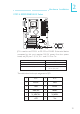


Table Of Contents
- About this Manual
- Warranty
- Static Electricity Precautions
- Safety Measures
- About the Package
- Before Using the System Board
- Chapter 1 - Introduction
- Chapter 2 - Hardware Installation
- Chapter 3 - BIOS Setup
- Chapter 4 - Supported Software
- Appendix A - Enabling Hyper-Threading Technology
- Appendix B - Watchdog Timer
- Appendix C - System Error Message
- Appendix D - Troubleshooting

36
2
Hardware Installation
Serial Ports
The system board is equipped with an onboard serial port (COM
1) at location CN4. It is also equipped with three 9-pin connectors
at locations J16 (COM 2), J12 (COM 3) and J18 (COM 4). The
serial ports are RS-232 and/or RS-485 (COM 4 only) asynchronous
communication ports with 16C550A-compatible UARTs that can be
used with modems, serial printers, remote display terminals, and
other serial devices.
To connect J16, J12 or J18 connector, please refer to the following
description. The serial port may be mounted on a card-edge bracket.
Install the card-edge bracket to an available slot at the rear of the
system chassis then insert the cable connector to J16, J12 or J18.
Make sure the colored stripe on the ribbon cable is aligned with pin
1 of J16, J12 or J18..
Jumper Setting
Use JP4 and/or JP5 to set COM 2 and/or COM 4 to RS-232 and/
or RS-485. Refer to “COM 2 RS232/AUX Select” and “COM 4
RS232/RS485/AUX Select” in this chapter for more information.
BIOS Setting
Configure the serial ports in the Integrated Peripherals submenu
(“Super IO Device” section) of the BIOS. Refer to chapter 3 for
more information.
COM 1
W
W
COM 3
COM 2
COM 4
1
9
2
CD
TD
GND
RTS
RI
RD
DTR
DSR
CTS