915G-TMGF 915GV-TML System Board User’s Manual 83800441
Copyright This publication contains information that is protected by copyright. No part of it may be reproduced in any form or by any means or used to make any transformation/adaptation without the prior written permission from the copyright holders. This publication is provided for informational purposes only.
Battery: • Danger of explosion if battery incorrectly replaced. • Replace only with the same or equivalent type recommend by the manufacturer. • Dispose of used batteries according to the batter y manufacturer’s instructions. FCC and DOC Statement on Class B This equipment has been tested and found to comply with the limits for a Class B digital device, pursuant to Part 15 of the FCC rules.
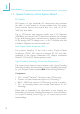
About this Manual This user’s manual contains detailed information about the system board. If, in some cases, some information doesn’t match those shown in the multilingual manual, the multilingual manual should always be regarded as the most updated version. The multilingual manual is included in the system board package. To view the user’s manual, insert the CD into a CD-ROM drive. The autorun screen (Mainboard Utility CD) will appear. Click the “TOOLS” icon then click “Manual” on the main menu.
Table of Contents Chapter 1 - Introduction 1.1 Specifications...................................................................................................................... 7 1.2 Special Features of the System Board..................................................... 10 1.3 Package Checklist......................................................................................................... 15 Chapter 2 - Hardware Installation 2.1 2.2 2.3 2.4 2.5 2.6 System Board Layout .......................
1 Introduction Appendix A - Enabling the Hyper-Threading Technology A.1 Enabling the Hyper-Threading Technology........................................... 109 Appendix B - System Error Messages B.1 POST Beep.................................................................................................................... 112 B.2 Error Messages........................................................................................................... 112 Appendix C - Troubleshooting C.
Introduction 1 Chapter 1 - Introduction 1.
1 Introduction - Wake-On-Ring (external modem) - Wake-On-LAN - RTC timer to power-on the system • AC power failure recovery Hardware Monitor • Monitors CPU/system temperature and overheat alarm • Monitors Vcore/V3SB/Vcc3/Vcc5/12V/V5SB/VBAT voltages • Monitors the speed of the CPU/system fan • CPU Overheat Protection function monitors CPU temperature and fan during system boot-up - automatic shutdown upon system overheat Onboard VGA Features • Built-in Intel Graphics Media Accelerator 900 Onboard Audio Feat
Introduction 1 IDE Interface • One IDE connector supports up to two UltraDMA100Mbps hard drives Rear Panel I/O Ports • 1 mini-DIN-6 PS/2 mouse port • 1 mini-DIN-6 PS/2 keyboard port • 1 DB-9 serial port • 1 DB-25 parallel por t • 1 DB-15 VGA port • 1 IEEE 1394 port (915G-TMGF only) • 1 RJ45 LAN port • 4 USB 2.0/1.1 ports • Line-in, line-out and mic-in jacks I/O Connectors • 2 connectors for 4 additional external USB 2.0/1.
1 Introduction 1.2 Special Features of the System Board PCI Express PCI Express is a high bandwidth I/O infrastructure that possesses the ability to scale speeds by forming multiple lanes. The system board currently supports the physical layer of x1 and x16 (915GTMGF only) lane widths. The x1 PCI Express lane supports transfer rate of 2.5 Gigabytes (250MBbps) per second.
Introduction 1 CPU Overheat Protection CPU Overheat Protection has the capability of monitoring the CPU’s temperature during system boot up. Once the CPU’s temperature exceeded the temperature limit pre-defined by the CPU, the system will automatically shutdown. This preventive measure has been added to protect the CPU from damage and insure a safe computing environment.
1 Introduction IEEE 1394 Interface (915G-TMGF only) IEEE 1394 is fully compliant with the 1394 OHCI (Open Host Controller Interface) 1.1 specification. It supports up to 63 devices that can run simultaneously on a system. 1394 is a fast external bus standard that supports data transfer rates of up to 400Mbps. In addition to its high speed, it also supports isochronous data transfer which is ideal for video devices that need to transfer high levels of data in real-time.
Introduction 1 Wake-On-LAN This feature allows the network to remotely wake up a Soft Power Down (Soft-Off) PC. It is supported via the onboard LAN port or via a PCI LAN card that uses the PCI PME (Power Management Event) signal. However, if your system is in the Suspend mode, you can power-on the system only through an IRQ or DMA interrupt. Important: The 5VSB power source of your power supply must support ≥720mA.
1 Introduction ACPI STR The system board is designed to meet the ACPI (Advanced Configuration and Power Interface) specification. ACPI has energy saving features that enables PCs to implement Power Management and Plug-and-Play with operating systems that support OS Direct Power Management. Currently, only Windows® 2000/XP supports the ACPI function. ACPI when enabled in the Power Management Setup will allow you to use the Suspend to RAM function.
Introduction 1 1.3 Package Checklist ; ; ; ; ; ; ; ; One system board One IDE cable for UltraDMA 33/66/100 IDE drives One 34-pin floppy disk drive cable Two Serial ATA data cables One Serial ATA power cable One I/O shield One “Mainboard Utility” CD One user’s manual If any of these items are missing or damaged, please contact your dealer or sales representative for assistance.
2 Hardware Installation Chapter 2 - Hardware Installation 2.
Hardware Installation 2 CPU fan PS/2 power select (JP3) KB Mouse 1 COM 1 DDR 2 DDR 1 DDR 4 DDR 3 +12V power ITE IT8712F 1 LGA 775 CPU Socket Parallel ATX power FDD VGA 1 1 USB 1 USB 2 1 LAN USB 3 USB 4 1 USB 1-4 power select (JP2) IrDA Intel 915GV Line-in Line-out Mic-in 1 IDE PCI 1 Realtek RTL8100C SATA 3 Intel ICH6 PCI 2 1 SATA 2 1 SATA 1 1 CD-in Front panel SATA 4 1 PCIE x1 Audio CODEC 1 1 1 USB 5-6 USB 7-8 USB 5-8 power select (JP1) 1 Clear CMOS (JP4) Chassi
2 Hardware Installation . . . . . . . . Warning: Electrostatic discharge (ESD) can damage your system board, processor, disk drives, add-in boards, and other components. Perform the upgrade instruction procedures described at an ESD workstation only. If such a station is not available, you can provide some ESD protection by wearing an antistatic wrist strap and attaching it to a metal part of the system chassis.
Hardware Installation 2 The system board supports the following memory interface. Single Channel (SC) Data will be accessed in chunks of 64 bits (8B) from the memory channels. Virtual Single Channel (VSC) If both channels are populated with different memory configurations, the MCH defaults to Virtual Single Channel. Dual Channel (DC) Dual channel provides better system performance because it doubles the data transfer rate.
2 Hardware Installation The table below lists the various optimal operating modes that should be configured for the memory channel operation.
Hardware Installation DDR 1 DDR 2 DDR 3 DDR 4 Dynamic Mode Addressing E P(*)(2,4) DS E P(*)(2,4) DS Dynamic Mode Addressing P(*)(1,3) DS E P(*)(1,3) DS E Dynamic Mode Addressing P(*)(1,3) DS P(*)(2,4) DS P(*)(1,3) DS P(*)(2,4) DS Dynamic Mode Addressing E P(*)(2,4) SS E P(*)(2,4) SS Dynamic Mode Addressing P(*)(1,3) SS E P(*)(1,3) SS E Dynamic Mode Addressing P(*)(1,3) SS P(*)(2,4) SS P(*)(1,3) SS P(*)(2,4) SS Config 2 P - denotes populated E - denotes empty * - denotes D
2 Hardware Installation 2.2.1 Installing the DIMM A DIMM simply snaps into a DIMM socket on the system board. Pin 1 of the DIMM must correspond with Pin 1 of the socket. Notch Key Tab Tab Pin 1 1. Pull the “tabs” which are at the ends of the socket to the side. 2. Position the DIMM above the socket with the “notch” in the module aligned with the “key” on the socket. 3. Seat the module vertically into the socket. Make sure it is completely seated. The tabs will hold the DIMM in place.
Hardware Installation 2 2.3 CPU 2.3.1 Overview The system board is equipped with a surface mount LGA 775 socket. This socket is exclusively designed for installing a LGA 775 packaged Prescott CPU. Important: 1. Before you proceed, make sure (1) the LGA775 socket comes with a protective cap, (2) the cap is not damaged and (3) the socket’s contact pins are not bent. If the cap is missing or the cap and/or contact pins are damaged, contact your dealer immediately immediately.. 2.
2 Hardware Installation Important: The CPU socket must not come in contact with anything other than the CPU. Avoid unnecessary exposure. Remove the protective cap only when you are about to install the CPU. 4. The CPU socket comes with a cover that is attached with a removable protective cap. The cap is used to protect the CPU socket against dust and harmful particles. Remove the protective cap only when you are about to install the CPU. Cover Protective cap Lever 5.
Hardware Installation 2 7. Now lift the cover. Cover 8. Position the CPU above the socket. The gold mark on the CPU must align with pin 1 of the CPU socket. Important: Handle the CPU by its edges and avoid touching the pins.
2 Hardware Installation 9. Insert the CPU into the socket until it is seated in place. The CPU will fit in only one orientation and can easily be inserted without exerting any force. Important: Do not force the CPU into the socket. Forcing the CPU into the socket may bend the pins and damage the CPU. 10. Once the CPU is in place, move the cover down.
Hardware Installation 2 11. Push the lever down to lock the socket. The lever should hook onto the side tab to indicate that the CPU is completely secured in the socket. 2.3.3 Installing the Fan and Heat Sink The CPU must be kept cool by using a CPU fan with heat sink. Without sufficient air circulation across the CPU and heat sink, the CPU will overheat damaging both the CPU and system board. Note: • Use only certified fan and heat sink.
2 Hardware Installation 2. Place the heat sink on top of the CPU. The 4 studs around the heat sink which are used to secure the heat sink onto the system board must match the 4 mounting holes around the socket. Position each stud so that the groove faces the heat sink then push it down firmly until it clicks into place. Note: You will not be able to secure the fan and heat sink assembly in place if the groove is not facing the heat sink.
Hardware Installation 2 2.4 Jumper Settings 2.4.1 Clear CMOS Data 3 2 1 1-2 On: Normal (default) 3 JP4 X 2 1 2-3 On: Clear CMOS Data If you encounter the following, a) CMOS data becomes corrupted. b) You forgot the supervisor or user password. c) You are unable to boot-up the computer system because the processor’s ratio/clock was incorrectly set in the BIOS. you can reconfigure the system with the default values stored in the ROM BIOS.
2 Hardware Installation 4. After powering-on the system, press to enter the main menu of the BIOS. 5. Select the Frequency/Voltage Control submenu and press . 6. Set the processor’s clock/ratio to its default setting or an appropriate bus clock or ratio. Refer to the Frequency/Voltage Control section in chapter 3 for more information. 7. Press to return to the main menu of the BIOS setup utility. Select “Save & Exit Setup” and press . 8. Type and press .
Hardware Installation 2 2.4.2 PS/2 Power Select JP3 X 1 1 2 2 3 3 1-2 On: 5V (default) 2-3 On: 5VSB JP3 is used to select the power of the PS/2 keyboard/mouse port. Selecting 5VSB will allow you to use the PS/2 keyboard or PS/2 mouse to wake up the system. BIOS Setting Configure the PS/2 keyboard/mouse wake up function in the Integrated Peripherals submenu (“Super IO Device” section) of the BIOS. Refer to chapter 3 for more information.
2 Hardware Installation 2.4.3 USB Power Select USB 1-4 (JP2) 1 1 2 2 3 3 X 1-2 On: 5V (default) 3 USB 5-8 (JP1) 2 1 1-2 On: 5V X (default) 2-3 On: 5VSB 3 2 1 2-3 On: 5VSB JP1 and JP2 are used to select the power of the USB ports. Selecting 5VSB will allow you to use the USB keyboard or USB mouse to wake up the system. BIOS Setting “USB KB Wake-Up From S3” in the Power Management Setup submenu of the BIOS must be set to Enabled. Refer to chapter 3 for more information.
Hardware Installation 2 2.
2 Hardware Installation 2.5.1 PS/2 Mouse and PS/2 Keyboard Ports PS/2 Mouse W PS/2 Keyboard The system board is equipped with an onboard PS/2 mouse (Green) and PS/2 keyboard (Purple) ports - both at location CN7 of the system board. The PS/2 mouse port uses IRQ12. If a mouse is not connected to this port, the system will reserve IRQ12 for other expansion cards. . . . . . . . . Warning: Make sure to turn off your computer prior to connecting or disconnecting a mouse or keyboard.
Hardware Installation 2 2.5.2 Serial Port W COM The system board is equipped with an onboard serial port (Teal/ Turquoise) at location CN5. The serial por t is an RS-232C asynchronous communication por t with 16C550A-compatible UARTs that can be used with a modem, serial printer, remote display terminal or other serial devices. BIOS Setting Select the serial port’s I/O address in the Integrated Peripherals submenu (“Super IO Device” section) of the BIOS. Refer to chapter 3 for more information.
2 Hardware Installation 2.5.3 Parallel Port Parallel W The system board has a standard parallel port (Burgundy) at location CN4 for interfacing your PC to a parallel printer. It supports SPP, ECP and EPP. Setting Function SPP (Standard Parallel Port) Allows normal speed operation but in one direction only. ECP (Extended Capabilities Port) Allows parallel port to operate in bidirectional mode and at a speed faster than the SPP’s data transfer rate.
Hardware Installation 2 2.5.4 VGA Port W VGA The system board can only be used with an analog video monitor. Connect the monitor’s 15-pin D-shell cable connector to the VGA port (Blue) at location CN6. If your monitor supports analog video but does not have a 15-pin D-shell connector, see your monitor dealer for the adapter or optional cable. After you plug the monitor cable into the VGA port, gently tighten the cable screws to hold the connector in place.
2 Hardware Installation 2.5.5 IEEE 1394 (915G-TMGF only) W Key +12V TPB+ Ground TPA+ 1394_1 1W 2 Ground +12V TPBGround TPA- 9 1394_2 1 0 The 915G-TMGF system board is equipped with an onboard IEEE 1394 port at location CN1 (IEEE 1394_1) of the system board. It is also equipped with an IEEE 1394 connector at location J1 (1394_2) for connecting an additional 1394 port. The 1394 port may be mounted on a card-edge bracket.
Hardware Installation 2 2.5.6 USB Ports USB 2 USB 1 W W Key Ground +Data -Data VCC USB 4 USB 3 1 2W N. C. Ground +Data -Data VCC 9 10 USB 5-6 USB 7-8 The system board supports 8 USB 2.0/1.1 ports. USB allows data exchange between your computer and a wide range of simultaneously accessible external Plug and Play peripherals. Four onboard USB 2.0/1.1 ports (Black) are at locations CN1 (USB 1-2) and CN2 (USB 3-4) of the system board.
2 Hardware Installation Driver Installation You may need to install the proper drivers in your operating system to use the USB device. Refer to your operating system’s manual or documentation for more information. Refer to chapter 4 for more information about installing the USB 2.0 driver. Wake-On-USB Keyboard/Mouse The Wake-On-USB Keyboard/Mouse function allows you to use a USB device to wake up a system from the S3 (STR - Suspend To RAM) state.
Hardware Installation 2 2.5.7 RJ45 LAN Port LAN W The RJ45 LAN port is at location CN2 of the system board. LAN allows the system board to connect to a local area network by means of a network hub. 915G-TMGF supports 1Gbps Gigabit LAN. 915GV-TML supports 10/100Mbps PCI LAN. BIOS Setting Configure the onboard LAN in the in the Integrated Peripherals submenu (“Onboard Device” section) of the BIOS. Refer to chapter 3 for more information. Driver Installation Install the Realtek LAN Drivers.
2 Hardware Installation 2.5.8 Audio (Rear Audio and Front Audio) Line-in Line-out Rear Audio W GND AuD_Vcc AuD_R_Return Key AuD_L_Return Mic-in Front audio 10 9 W Mic N. C. AuD_R_Out N. C. AuD_L_Out 2 1 Rear Panel Audio • Line-in (Light Blue) In a 2-channel or 4-channel mode, this jack is used to connect any audio devices such as Hi-fi set, CD player, tape player, AM/ FM radio tuner, synthesizer, etc. In a 6-channel mode, this jack functions as Center/Subwoofer.
Hardware Installation 2-channel 4-channel 6-channel Line-in Line-in Center/Subwoofer Lime Line-out Front R/L Front R/L Pink Mic-in Rear R/L Rear R/L Light Blue 2 Front Audio The front audio connector (J4) allows you to connect to the line-out and mic-in jacks that are at the front panel of your system. Using this connector will disable the rear audio’s line-out and mic-in functions. Remove the jumper caps from pins 5-6 and pins 9-10 of J4 prior to connecting the front audio cable connector.
2 Hardware Installation 2.6 I/O Connectors 2.6.1 CD-in Internal Audio Connector Ground Ground Right audio Left audio channel channel 4 1 W The CD-in (J6) connector is used to receive audio from a CD-ROM drive, TV tuner or MPEG card.
Hardware Installation 2 2.6.2 S/PDIF SPDIF out Key GND +5V SPDIF in 1 5 W The system board is equipped with a S/PDIF connector. One cardedge bracket, mounted with S/PDIF ports, may be provided with the system board. Install the card-edge bracket to the system chassis then connect the audio cable connector to J5. Make sure pin 1 of the audio cable connector is aligned with pin 1 of J5.
2 Hardware Installation 2.6.3 Floppy Disk Drive Connector 34 33 X 2 1 The system board is equipped with a shrouded floppy disk drive connector that supports two standard floppy disk drives. To prevent improper floppy cable installation, the shrouded floppy disk header has a keying mechanism. The 34-pin connector on the floppy cable can be placed into the header only if pin 1 of the connector is aligned with pin 1 of the header.
Hardware Installation 2 2.6.4 Serial ATA Connectors 1 7 SATA 4 1 7 1 7 SATA 2 X1 SATA 1 GND TXP TXN GND RXN RXP GND 7 SATA 3 The system board is equipped with four Serial ATA connectors for connecting Serial ATA devices. Connect one end of the Serial ATA cable to J15 (SATA 1), J16 (SATA 2), J17 (SATA 3) or J18 (SATA 4) and the other end to your Serial ATA device. BIOS Setting Configure the Serial ATA drives in the Integrated Peripherals submenu (“OnChip IDE Device” field) of the BIOS.
2 Hardware Installation 2.6.5 IDE Disk Drive Connector 40 39 X 2 1 The system board is equipped with a shrouded PCI IDE header that will interface two Enhanced IDE (Integrated Drive Electronics) disk drives. To prevent improper IDE cable installation, the shrouded PCI IDE header has a keying mechanism. The 40-pin connector on the IDE cable can be placed into the header only if pin 1 of the connector is aligned with pin 1 of the header. The IDE connector supports 2 devices, a Master and a Slave.
Hardware Installation 2 Adding a Second IDE Disk Drive When using two IDE drives, one must be set as the master and the other as the slave. Follow the instructions provided by the drive manufacturer for setting the jumpers and/or switches on the drives. The system board suppor ts Enhanced IDE or ATA-2, ATA/33, ATA/66 or ATA/100 hard drives. We recommend that you use hard drives from the same manufacturer.
2 Hardware Installation 2.6.6 IrDA Connector 1 X 5 VCC N. C. IRRX Ground IRTX Connect the cable connector from your IR module to the IR connector (J13). Note: The sequence of the pin functions on some IR cable may be reversed from the pin function defined on the system board. Make sure to connect the cable connector to the IR connector according to their pin functions. BIOS Setting Configure IR in the Integrated Peripherals submenu (“Super IO Device” field) of the BIOS.
Hardware Installation 2 2.6.7 Cooling Fan Connectors X 4 1 Speed Ground Control Power Sense CPU fan Sense Power X Ground 3 1 Chassis fan Connect the CPU fan’s cable connector to the CPU fan connector (J8) on the system board. The chassis fan connector (J10) is used to connect an additional cooling fan. The cooling fan will provide adequate airflow throughout the chassis to prevent overheating the CPU and system board components.
2 Hardware Installation 2.6.8 Power Connectors 3 4 +12V +12V Ground XGround 1 2 12 24 COM +5VDC +5VDC +5VDC NC COM COM COM PS_ON# COM -12VDC +3.3VDC +3.3VDC +12VDC +12VDC +5VSB PWR_OK X COM +5VDC COM +5VDC COM +3.3VDC +3.3VDC 1 13 We recommend that you use a power supply that complies with the ATX12V Power Supply Design Guide Version 1.1.
Hardware Installation 2 2.6.9 Front Panel Connectors 2 01 9 SPEAKER J19 X RESET ATX-SW HD-LED PWR-LED 21 HD-LED: Primary/Secondary IDE LED This LED will light when the hard drive is being accessed. RESET: Reset Switch This switch allows you to reboot without having to power off the system thus prolonging the life of the power supply or system. SPEAKER: Speaker Connector This connects to the speaker installed in the system chassis.
2 Hardware Installation PWR-LED: Power/Standby LED When the system’s power is on, this LED will light. When the system is in the S1 (POS - Power On Suspend) or S3 (STR - Suspend To RAM) state, it will blink every second. Note: If a system did not boot-up and the Power/Standby LED did not light after it was powered-on, it may indicate that the CPU or memory module was not installed properly. Please make sure they are properly inserted into their corresponding socket.
Hardware Installation 2 2.6.10 PCI Express x16 and x1 Slots PCI Express x16 (915G-TMGF only) PCI Express x1 915G-TMGF is equipped with one PCI Express x16 and one PCI Express x1 slots. 915GV-TML is only equipped with one PCI Express x1 slot. PCI Express x16 Install PCI Express x16 graphics card, that comply to the PCI Express specifications, into the PCI Express x16 slot.
3 BIOS Setup Chapter 3 - BIOS Setup 3.1 Award BIOS Setup Utility The Basic Input/Output System (BIOS) is a program that takes care of the basic level of communication between the processor and peripherals. In addition, the BIOS also contains codes for various advanced features found in this system board. This chapter explains the Setup Utility for the Award BIOS. After you power up the system, the BIOS message appears on the screen and the memory count begins.
BIOS Setup 3 3.1.1 Standard CMOS Features Use the arrow keys to highlight “Standard CMOS Features” and press . A screen similar to the one below will appear. The settings on the screen are for reference only. Your version may not be identical to this one. 3.1.1.1 Date The date format is , , , . Day displays a day, from Sunday to Saturday. Month displays the month, from January to December. Date displays the date, from 1 to 31. Year displays the year, from 1990 to 2098. 3.
3 BIOS Setup 3.1.1.3 IDE Channel 0 Master/Slave and IDE Channel 1 Master/Slave Move the cursor to the “IDE Channel 0 Master”, “IDE Channel 0 Slave”, “IDE Channel 1 Master” or “IDE Channel 1 Slave” field, then press . The settings on the screen are for reference only. Your version may not be identical to this one. IDE HDD Auto Detection Detects the parameters of the drive. The parameters will automatically be shown on the screen.
BIOS Setup 3 Access Mode For hard drives larger than 528MB, you would typically select the LBA type. Certain operating systems require that you select CHS or Large. Please check your operating system’s manual or Help desk on which one to select. Capacity Displays the approximate capacity of the disk drive. Usually the size is slightly greater than the size of a formatted disk given by a disk checking program. Cylinder This field displays the number of cylinders.
3 BIOS Setup 3.1.1.5 Video This field selects the type of video adapter used for the primary system monitor. Although secondary monitors are supported, you do not have to select the type. The default setting is EGA/VGA. EGA/VGA Enhanced Graphics Adapter/Video Graphics Array. For EGA, VGA, SVGA and PGA monitor adapters. CGA 40 Color Graphics Adapter. Power up in 40-column mode. CGA 80 Color Graphics Adapter. Power up in 80-column mode. Mono Monochrome adapter. Includes high resolution monochrome adapters.
BIOS Setup 3 3.1.1.8 Extended Memory Displays the amount of extended memory detected during boot-up. 3.1.1.9 Total Memory Displays the total memory available in the system.
3 BIOS Setup 3.1.2 Advanced BIOS Features The Advanced BIOS Features allows you to configure your system for basic operation. Some entries are defaults required by the system board, while others, if enabled, will improve the performance of your system or let you set some features according to your preference. The screen above list all the fields available in the Advanced BIOS Features submenu, for ease of reference in this manual.
BIOS Setup 3 3.1.2.1 CPU Feature Move the cursor to this field and press . The following screen will appear. The settings on the screen are for reference only. Your version may not be identical to this one. Delay Prior To Thermal This field is used to select the time that would force the CPU to a 50% duty cycle when it exceeds its maximum operating temperature therefore protecting the CPU and the system board from overheating to ensure a safe computing environment..
3 BIOS Setup Limit CPUID MaxVal The CPUID instruction of some newer CPUs will return a value greater than 3. The default is Disabled because this problem does not exist in the Windows series operating systems. If you are using an operating system other than Windows, this problem may occur. To avoid this problem, enable this field to limit the return value to 3 or lesser than 3. NX BIOS Control The default is Enabled. When this function is disabled, it forces the NX features flag to always return to 0. 3.1.
BIOS Setup 3 3.1.2.3 Virus Warning This field protects the boot sector and partition table of your hard disk drive. When this field is enabled, the Award BIOS will monitor the boot sector and partition table of the hard disk drive. If an attempt is made to write to the boot sector or partition table of the hard disk drive, the BIOS will halt the system and an error message will appear.
3 BIOS Setup 3.1.2.8 First Boot Device, Second Boot Device, Third Boot Device and Boot Other Device Select the drive to boot first, second and third in the “First Boot Device” “Second Boot Device” and “Third Boot Device” fields respectively. The BIOS will boot the operating system according to the sequence of the drive selected. Set “Boot Other Device” to Enabled if you wish to boot from another device. 3.1.2.
BIOS Setup 3 3.1.2.13 Typematic Rate Setting Disabled Continually holding down a key on your keyboard will cause the BIOS to report that the key is down. Enabled The BIOS will not only report that the key is down, but will first wait for a moment, and, if the key is still down, it will begin to report that the key has been depressed repeatedly. For example, you would use such a feature to accelerate cursor movements with the arrow keys.
3 BIOS Setup 3.1.2.18 MPS Version Control for OS This field is used to select the MPS version that the system board is using. 3.1.2.19 OS Select for DRAM > 64MB This field allows you to access the memory that is over 64MB in OS/2. 3.1.2.20 Report No FDD For WIN 95 The options are Yes and No. 3.1.2.21 Small Logo(EPA) Show Enabled The EPA logo will appear during system boot-up. Disabled The EPA logo will not appear during system boot-up.
BIOS Setup 3 3.1.3 Advanced Chipset Features The settings on the screen are for reference only. Your version may not be identical to this one. This section gives you functions to configure the system based on the specific features of the chipset. The chipset manages bus speeds and access to system memory resources. These items should not be altered unless necessary. The default settings have been chosen because they provide the best operating conditions for your system.
3 BIOS Setup select the best option in the “CAS Latency Time” to “System Memory Frequency” fields. 3.1.3.2 CAS Latency Time This field is used to select the latency between the DRAM read command and the time that the data was received. 3.1.3.3 DRAM RAS# to CAS# Delay This field is used to select the latency between the DRAM active command and the read/write command. 3.1.3.4 DRAM RAS# Precharge This field is used to select the idle clocks after issuing a precharge command to the DRAM. 3.1.3.
BIOS Setup 3 3.1.3.10 Memory Hole At 15M-16M In order to improve system performance, certain space in memory can be reserved for ISA cards. This memory must be mapped into the memory space below 16MB. When enabled, the CPU assumes the 1516MB memory range is allocated to the hidden ISA address range instead of the actual system DRAM. When disabled, the CPU assumes the 15-16MB address range actually contains DRAM memory.
3 BIOS Setup 3.1.3.12 PEG/Onchip VGA Control This field is used to select the graphics controller that will serve as the primary boot device. The options are Auto, Onchip VGA and PEG Port. 3.1.3.13 PEG Force X1 The options are Enabled and Disabled. 3.1.3.14 On-Chip Video Memory Size This field is used to select the graphics memory size. 3.1.3.15 On-Chip Frame Buffer Size This field is used to select the onboard VGA’s frame buffer size that is shared from the system memory. 3.1.3.
BIOS Setup 3 3.1.3.19 Boot Display This field is used to select the type of display to use when the system boots. Auto CRT TV EPP The system will automatically detect the display that is available when the system boots. Select this option if you want the system to boot the CRT display. Select this option if you want the system to boot the TV display. Select this option if you want the system to boot the EPP display.
3 BIOS Setup 3.1.4 Integrated Peripherals The settings on the screen are for reference only. Your version may not be identical to this one. 3.1.4.1 OnChip IDE Device Move the cursor to this field and press . The following screen will appear. The settings on the screen are for reference only. Your version may not be identical to this one.
BIOS Setup 3 IDE HDD Block Mode Enabled Disabled The IDE HDD uses the block mode. The system BIOS will check the hard disk drive for the maximum block size the system can transfer. The block size will depend on the type of hard disk drive. The IDE HDD uses the standard mode. IDE DMA Transfer Access This field, when Enabled, will enhance the IDE DMA transfer of an IDE hard disk drive. On-Chip Primary PCI IDE These fields allow you to enable or disable the primary and secondary IDE controller.
3 BIOS Setup On-Chip Serial ATA Setting On-Chip Serial ATA Disabled Auto Disables the onboard SATA. The system will detect the existing SATA and IDE drives then automatically set them to the available master/slave mode. Combined Mode This option allows you to use both IDE and SATA drives; allowing a maximum of 4 drives 1 IDE Master, 1 IDE Slave and 2 SATA. You must manually set the SATA and PATA drives’ mode in the “PATA IDE Mode” and “SATA Port” fields.
BIOS Setup 3 SATA Port If the “PATA IDE Mode” field is set to Primary, this field will show “P1, P3 is Secondary”; meaning SATA 2 and SATA 4 are Secondary. If the “PATA IDE Mode” field is set to Secondary, this field will show “P0, P2 is Primary”; meaning SATA 1 and SATA 3 are Primary. 3.1.4.2 Onboard Device Move the cursor to this field and press . The following screen will appear. The settings on the screen are for reference only. Your version may not be identical to this one.
3 BIOS Setup AC97 Audio Auto Select this option when using the onboard audio CODEC. Disabled Select this option when using a PCI sound card. Onboard LAN Control This field is used to enable or disable the onboard LAN.
BIOS Setup 3 3.1.4.3 Super IO Device Move the cursor to this field and press . The following screen will appear. The settings on the screen are for reference only. Your version may not be identical to this one. Power On Function This field allows you to use the keyboard or PS/2 mouse to poweron the system. Button only Default setting. Uses the power button to power on the system.
3 BIOS Setup KB Power On Password Move the cursor to this field and press . Enter your password. You can enter up to 5 characters. Type in exactly the same password to confirm, then press . The power button will not function once a keyboard password has been set in this field. You must type the correct password to poweron the system. If you forgot the password, power-off the system and remove the battery. Wait for a few seconds and install it back before powering-on the system.
BIOS Setup 3 Onboard Parallel Port 378/IRQ7, 3BC/IRQ7, 278/IRQ5 Selects the I/O address and IRQ for the onboard parallel port. Disabled Disables the onboard parallel port. Parallel Port Mode The options are SPP, EPP, ECP and ECP+EPP. These apply to a standard specification and will depend on the type and speed of your device. Refer to your peripheral’s manual for the best option. SPP Allows normal speed operation but in one direction only.
3 BIOS Setup 3.1.5 Power Management Setup The Power Management Setup allows you to configure your system to most effectively save energy. The screen above list all the fields available in the Power Management Setup submenu, for ease of reference in this manual. In the actual CMOS setup, you have to use the scroll bar to view the fields. The settings on the screen are for reference only. Your version may not be identical to this one. 3.1.5.
BIOS Setup 3 3.1.5.4 Power Management This field allows you to select the type (or degree) of power saving by changing the length of idle time that elapses before the Suspend mode and HDD Power Down fields are activated. Min Saving Max Saving User Define Minimum power saving time for the Suspend Mode (1 hour) and HDD Power Down (15 min.) Maximum power saving time for the. Suspend Mode and HDD Power Down = 1 min. Allows you to set the power saving time in the “Suspend Mode” and “HDD Power Down” fields.
3 BIOS Setup 3.1.5.9 Suspend Mode This is selectable only when the Power Management field is set to User Define. When the system enters the Suspend mode according to the power saving time selected, the CPU and onboard peripherals will be shut off. 3.1.5.10 HDD Power Down This is selectable only when the Power Management field is set to User Define.
BIOS Setup 3 3.1.5.13 Wake-Up By PCI Card Enabled This field should be set to Enabled only if your PCI card such as LAN card or modem card uses the PCI PME (Power Management Event) signal to remotely wake up the system. Access to the LAN card or PCI card will cause the system to wake up. Refer to the card’s documentation for more information. Disabled The system will not wake up despite access to the PCI card. 3.1.5.14 Power On By Ring Set this field to Enabled to use the modem ring-on function.
3 BIOS Setup 3.1.5.18 Time (hh:mm:ss) Alarm This is used to set the time you would like the system to power-on. If you want the system to power-on everyday as set in the “Date (of Month) Alarm” field, the time set in this field must be later than the time of the RTC set in the Standard CMOS Features submenu. 3.1.5.
BIOS Setup 3 3.1.6 PnP/PCI Configurations This section describes configuring the PCI bus system. It covers some very technical items and it is strongly recommended that only experienced users should make any changes to the default settings. The settings on the screen are for reference only. Your version may not be identical to this one. 3.1.6.1 Init Display First This field is used to select whether to initialize the onboard VGA, PCI Express or PCI first when the system boots.
3 BIOS Setup 3.1.6.3 Resources Controlled By The Award Plug and Play BIOS has the capability to automatically configure all of the boot and Plug and Play compatible devices. Auto Manual The system will automatically detect the settings for you. Choose the specific IRQ in the “IRQ Resources” field respectively. 3.1.6.4 IRQ Resources Move the cursor to this field and press . This field is used to set each system interrupt to either Reserved or PCI Device.
BIOS Setup 3 3.1.6.7 Maximum Payload Size This field is used to select the maximum TLP payload size of the PCI Express devices. The unit is byte.
3 BIOS Setup 3.1.7 PC Health Status The settings on the screen are for reference only. Your version may not be identical to this one. 3.1.7.1 Shutdown Temperature You can prevent the system from overheating by selecting a temperature in this field. If the system detected that its temperature exceeded the one set in this field, it will automatically shutdown. This function will work only when you enable this function in the Hardware Monitor utility. 3.1.7.
BIOS Setup 3 3.1.8 Frequency/Voltage Control The settings on the screen are for reference only. Your version may not be identical to this one. 3.1.8.1 CPU Clock Ratio This field is used to select the CPU’s frequency ratio. Important: The frequency ratio of some processors may have been locked by the manufacturer. If you are using this kind of processor, setting a frequency ratio for the processor will have no effect. The system will instead use its factory default ratio. 3.1.8.
3 BIOS Setup 3.1.8.4 CPU Clock This field provides several options for selecting the external system bus clock of the processor. The available options allow you to adjust the processor’s bus clock by 1MHz increment. Important: Selecting an external bus clock other than the default setting may result to the processor’s or system’s instability and are not guaranteed to provide better system performance.
BIOS Setup 3 3.1.9 Load Fail-Safe Defaults The “Load Fail-Safe Defaults” option loads the troubleshooting default values permanently stored in the ROM chips. These settings are not optimal and turn off all high performance features. You should use these values only if you have hardware problems. Highlight this option in the main menu and press . If you want to proceed, type and press . The default settings will be loaded.
3 BIOS Setup 3.1.10 Load Optimized Defaults The “Load Optimized Defaults” option loads optimized settings from the BIOS ROM. Use the default values as standard values for your system. Highlight this option in the main menu and press . Type and press to load the Setup default values.
BIOS Setup 3 3.1.11 Set Supervisor Password If you want to protect your system and setup from unauthorized entry, set a supervisor’s password with the “System” option selected in the Advanced BIOS Features. If you want to protect access to setup only, but not your system, set a supervisor’s password with the “Setup” option selected in the Advanced BIOS Features. You will not be prompted for a password when you cold boot the system.
3 BIOS Setup 3.1.12 Set User Password If you want another user to have access only to your system but not to setup, set a user’s password with the “System” option selected in the Advanced BIOS Features. If you want a user to enter a password when trying to access setup, set a user’s password with the “Setup” option selected in the Advanced BIOS Features. Using user’s password to enter Setup allows a user to access only “Set User Password” that appears in the main menu screen.
BIOS Setup 3 3.1.13 Save & Exit Setup When all the changes have been made, highlight “Save & Exit Setup” and press . Type “Y” and press . The modifications you have made will be written into the CMOS memory, and the system will reboot. You will once again see the initial diagnostics on the screen. If you wish to make additional changes to the setup, press simultaneously or after memory testing is done.
3 BIOS Setup 3.1.14 Exit Without Saving When you do not want to save the changes you have made, highlight “Exit Without Saving” and press . Type “Y” and press . The system will reboot and you will once again see the initial diagnostics on the screen. If you wish to make any changes to the setup, press simultaneously or after memory testing is done.
BIOS Setup 3 3.2 Updating the BIOS To update the BIOS, you will need the new BIOS file and a flash utility, AWDFLASH.EXE. You can download them from DFI’s web site or contact technical support or your sales representative. 1. Save the new BIOS file along with the flash utility AWDFLASH.EXE to a floppy disk. 2. Reboot the system and enter the Award BIOS Setup Utility to set the first boot drive to “Floppy”. 3. Save the setting and reboot the system. 4.
3 BIOS Setup 6. The following will appear. Do You Want to Save BIOS (Y/N) This question refers to the current existing BIOS in your system. We recommend that you save the current BIOS and its flash utility; just in case you need to reinstall the BIOS. To save the current BIOS, press then enter the file name of the current BIOS. Otherwise, press . 7. The following will then appear. Press “Y” to Program or “N” to Exit 8. Press to flash the new BIOS.
Supported Software 4 Chapter 4 - Supported Software 4.1 Drivers, Utilities and Software Applications The CD that came with the system board contains drivers, utilities and software applications required to enhance the performance of the system board. Inser t the CD into a CD-ROM drive. The autorun screen (Mainboard Utility CD) will appear.
4 Supported Software 4.1.1 Intel Chipset Software Installation Utility The Intel Chipset Software Installation Utility is used for updating Windows 2000/ME/XP's INF files so that the Intel chipset can be recognized and configured properly in the system. To install the utility, please follow the steps below. 1. On the left side of the autorun screen, click the “CHIPSET” icon. 2. Click “Intel Chipset Software Installation Utility” on the main menu. The following screen will appear. 3.
Supported Software 4 4.1.2 Intel Graphics Media Accelerator Driver To install the driver, please follow the steps below. 1. On the left side of the autorun screen, click the “GRAPHICS” icon. 2. Click “Intel Graphics Media Accelerator Driver” on the main menu. The following screen will appear. 3. Follow the prompts on the screen to complete installation. 4. Reboot the system for the driver to take effect.
4 Supported Software 4.1.3 Realtek Audio Driver To install the driver, please follow the steps below. 1. On the left side of the autorun screen, click the “AUDIO” icon. 2. Click “Realtek Audio Driver” on the main menu. The following screen will appear. 3. Follow the prompts on the screen to complete installation. 4. Reboot the system for the driver to take effect.
Supported Software 4 4.1.4 Realtek LAN Driver To install the driver, please follow the steps below. 1. On the left side of the autorun screen, click the “NETWORK” icon. 2. Click “Realtek LAN Driver” on the main menu. The following screen will appear. 3. Follow the prompts on the screen to complete installation. 4. Reboot the system for the driver to take effect.
4 Supported Software 4.1.5 Hardware Monitor The system board comes with the Hardware Monitor utility contained in the provided CD. This utility is capable of monitoring the system’s temperature, fan speed, voltage, etc. and allows you to manually set a range (Highest and Lowest Limit) to the items being monitored. If the settings/values are over or under the set range, a warning message will pop-up. The utility can also be configured so that a beeping alarm will sound whenever an error occurs.
Supported Software 4 4.1.6 Microsoft DirectX 9 To install, please follow the steps below. 1. On the left side of the autorun screen, click the “TOOLS” icon. 2. Click “Microsoft DirectX 9” on the main menu. The following screen will appear. 3. Click “I accept the agreement” then click “Next”. 4. Follow the prompts on the screen to complete installation. 5. Reboot the system for the driver to take effect.
4 Supported Software 4.1.7 Intel USB 2.0 Drivers The Intel chipset does not support USB 2.0 drivers for Windows 98 SE and Windows ME. Windows® XP If your Windows® XP CD already includes Service Pack 1, the USB 2.0 driver will automatically install when you install the operating system. If the CD does not include Service Pack 1, it is available for download at Microsoft’s Windows Update website. Windows® 2000 If your Windows® 2000 CD already includes Service Pack 4, the USB 2.
Enabling Hyper-Threading Technology A Appendix A - Enabling Hyper-Threading Technology A.1 Enabling Hyper-Threading Technology To enable the functionality of the Hyper-Threading Technology, please follow the requirements and steps below. Basically, the following presumes that you have already installed an Intel® Pentium® 4 Processor with Hyper-Threading Technology. 1. The system requires a minimum of 300 Watt ATX 12V power supply. 2.
A Enabling Hyper-Threading Technology c. Click the General tab. The processor shown under Computer should resemble the one shown below. d. Now click the Hardware tab then click Device Manager. The items shown under Computer and Processors should resemble the ones shown below.
Enabling Hyper-Threading Technology A e. Lastly, press the and keys simultaneously. The Windows Task Manager dialog box will appear. Click the Performance tab. The diagram under CPU Usage History should resemble the one shown below.
B System Error Message Appendix B - System Error Message When the BIOS encounters an error that requires the user to correct something, either a beep code will sound or a message will be displayed in a box in the middle of the screen and the message, PRESS F1 TO CONTINUE, CTRL-ALT-ESC or DEL TO ENTER SETUP, will be shown in the information box at the bottom. Enter Setup to correct the error. B.
System Error Message B Hard Disk(s) fail (80) HDD reset failed. Hard Disk(s) fail (40) HDD controller diagnostics failed. Hard Disk(s) fail (20) HDD initialization error. Hard Disk(s) fail (10) Unable to recalibrate fixed disk. Hard Disk(s) fail (08) Sector Verify failed. Keyboard is locked out - Unlock the key The BIOS detects that the keyboard is locked. Keyboard controller is pulled low. Keyboard error or no keyboard present Cannot initialize the keyboard.
C Troubleshooting Appendix C - Troubleshooting C.1 Troubleshooting Checklist This chapter of the manual is designed to help you with problems that you may encounter with your personal computer. To efficiently troubleshoot your system, treat each problem individually. This is to ensure an accurate diagnosis of the problem in case a problem has multiple causes. Some of the most common things to check when you encounter problems while using your system are listed below. 1.
Troubleshooting C The picture seems to be constantly moving. 1. The monitor has lost its vertical sync. Adjust the monitor’s vertical sync. 2. Move away any objects, such as another monitor or fan, that may be creating a magnetic field around the display. 3. Make sure your video card’s output frequencies are supported by this monitor. The screen seems to be constantly wavering. 1. If the monitor is close to another monitor, the adjacent monitor may need to be turned off.
C Troubleshooting Hard Drive Hard disk failure. 1. Make sure the correct drive type for the hard disk drive has been entered in the BIOS. 2. If the system is configured with two hard drives, make sure the bootable (first) hard drive is configured as Master and the second hard drive is configured as Slave. The master hard drive must have an active/bootable partition. Excessively long formatting period.
Troubleshooting C 3. Verify that the attached serial device works by attaching it to a serial port that is working and configured correctly. If the serial device does not work, either the cable or the serial device has a problem. If the serial device works, the problem may be due to the onboard I/O or the address setting. 4. Make sure the COM settings and I/O address are configured correctly. Keyboard Nothing happens when a key on the keyboard was pressed. 1. Make sure the keyboard is properly connected.
C 118 Troubleshooting