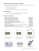
EasyTouch® 8 and 4 Pool and Spa Control System Indoor Control Panel AUTO HEATER SPA 100° F / 95° F AIR 77° F MON 09:30 AM Installation and User’s Guide IMPORTANT SAFETY INSTRUCTIONS READ AND FOLLOW ALL INSTRUCTIONS SAVE THESE INSTRUCTIONS
© 2011 Pentair Water Pool and Spa, Inc. All rights reserved This document is subject to change without notice 1620 Hawkins Ave., Sanford, NC 27330 • (800) 831-7133 • (919) 566-8000 10951 West Los Angeles Ave.
i Contents IMPORTANT WARNING AND SAFETY INSTRUCTIONS .................................................................. EasyTouch Indoor Control Panel Kit Contents .................................................................................. Related Manuals .............................................................................................................................. EasyTouch Accessories ...................................................................................................
ii Contents Settings Menu: IntelliFlo (VS and VSF +SVRS) ............................................................................... Settings Menu: IntelliFlo (VF) ........................................................................................................... Settings Menu: IntelliChlor ................................................................................................................ Settings Menu: IntelliChem ...................................................................
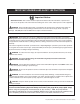
iii IMPORTANT WARNING AND SAFETY INSTRUCTIONS Important Notice: Attention Installer: This manual contains important information about the installation, operation and safe use of this product. This information should be given to the owner and/or operator of this equipment. WARNING - Before installing this product, read and follow all warning notices and instructions which are included. Failure to follow safety warnings and instructions can result in severe injury, death, or property damage.
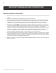
iv IMPORTANT WARNING AND SAFETY INSTRUCTIONS General Installation Information 1. All work must be performed by a licensed electrician, and must conform to all national, state, and local codes. 2. Install to provide drainage of compartment for electrical components. 3. If this system is used to control underwater lighting fixtures, a ground-fault circuit interrupter (GFCI) must be provided for these fixtures.
v EasyTouch Indoor Control Panel Kit Contents The following items are included in the EasyTouch indoor control panel kit. If any items are missing please contact Pentair Technical Support (see page vi).
vi Technical Support Contact Technical Support at: Sanford, North Carolina (8 A.M. to 5 P.M.) Phone: (800) 831-7133 Fax: (919) 566-8920 Moorpark, California (8 A.M. to 5 P.M.) Phone: (800) 831-7133 (Ext. 6312) Fax: (805) 553-5515 Web sites: visit www.pentairpool.com and www.staritepool.
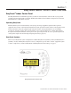
1 Section 1 EasyTouch Indoor Control Panel Overview EasyTouch® Indoor Control Panel The EasyTouch Indoor Control Panel provides you with one touch automatic control for all of your pool and spa daily operations from inside your home. The EasyTouch Indoor Control Panel is designed to be used with the EasyTouch 8 or EasyTouch 4 system. Operating EasyTouch The EasyTouch system can automatically control your pool and spa equipment, lights and other optional equipment.
2 EasyTouch Indoor Control Panel Overview The EasyTouch Indoor Control Panel makes it easy for you to control your pool and spa daily operations from inside your home. Using the “Pool” and “Spa” buttons allows one touch control to heat and filter your spa and pool. EasyTouch automatic system operations can be performed either at the Indoor Control Panel or from the outdoor control panel. The Indoor Control Panel connects to the motherboard in the EasyTouch load center.
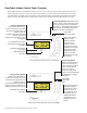
3 EasyTouch Indoor Control Panel Buttons You can fully automate your pool, spa, and lighting operations from the EasyTouch Indoor Control Panel or from the EasyTouch outdoor control panel located at the pool equipment pad. The EasyTouch menu features let you create customized schedules for your pool and spa equipment, heat temperatures, and chlorination settings to switch on and off at a set day and time.
4 Controls and buttons (Continued) Pool button (Continued) • Single-Speed Filter Pump: If the pump is currently off, press the Pool button to switch the pump on. Press the Pool button again to switch the pump off.
5 Controls and buttons (Continued) ➇ AUX buttons/LEDs: The auxiliary output circuit buttons operate the pool and spa system valve actuators, lights and other equipment. The auxiliary (AUX) relay circuits are assigned in the “Circuit Functions” menu, see page 37 for details. There are three auxiliary circuits (AUX 1- 3) on the EasyTouch 4 indoor control panel and seven auxiliary circuits (AUX 1- 7) on the EasyTouch 8 indoor control panel.
6 Quick Start - Pool and Spa Operations (Shared Equipment) The following describes how to adjust heat temperature for the spa and pool water, schedule a daily run time for the pool/spa filter pump and control lights. Heating the Spa Heating the spa water on demand is easy, just press the SPA button to switch the heater on and display the current temperature settings on the EasyTouch Indoor Control Panel. “Heater” will be displayed on the screen when the heater is active.
7 Quick Start - (Pool and Spa Operations (Shared Equipment) Continued Schedule start and stop times for equipment From the Schedules menu you can set the a start and stop time to automatically run pool and spa equipment and control underwater and backyard lights. For example, the filter pump relay circuit can be scheduled to run the daily pool and spa filtration at a specific time and day(s) of the week. Up to 12 total program schedules may be created for all relay circuits combined.
8 EasyTouch Wireless Control Panel (Accessory) The EasyTouch wireless control panel (8 or 4 circuits) gives you the freedom to control your pool and spa daily operations from around your pool and spa area. The wireless device can operate up to 300 feet from the EasyTouch transceiver module which is typically located near the EasyTouch load center.
9 SETTINGS CLOCK (OPTIONAL) INTELLIFLO PUMP #1 - PUMP TYPE [VF, VS, VSF, NONE] - VF: FILTR.
10 EasyTouch Menus From the EasyTouch control panel menus you can schedule everyday pool/spa, heating, filtration and cleaning. Lights and laminars can also be scheduled to switch on and off at specific times. The “Settings” and “Schedule” menus are typically used most often for daily spa and pool operations. The “Settings” menu is used by the pool installer to setup installed equipment which is connected to each output relay (filter pump, auxiliary relays, heater, valves, lights, etc.).
11 Feature Circuits Menu There are eight (8) “Feature Circuits” that can be used to control IntelliFlo® pump speeds or valves actuators for a spa spillway. Unlike an auxiliary relay circuit, a “Feature” circuit does not connect directly to a relay. “Feature” are turned on and off from the control panel “Feature” circuit menu. Feature Circuits Getting There ▲ Menu F. Circuits To switch a feature circuit ON or OFF: F.
12 Lights Menu From the Lights screen you can manually switch all lights on or off, and synchronize colored lights. Up to eight (8) lights (EasyTouch 8) or 4 lights (EasyTouch 4) can be independently controlled from the Lights screen. Each light requires a separate auxiliary relay circuit. Up to four lights can be assigned on each auxiliary circuit. A circuit name must be assigned to the AUX relay circuits which controls the light.
13 Setting up Lights The following section describes how to assign a light circuit name and function to control IntelliBrite, SAm and/or SAL, and/or FIBERworks lights. Assign the Light Circuit Name and Function The first step in setting up a light circuit is to assign a name to the relay circuit (example; AUX 3, as “Pool Light”), then assign the name “Pool Light” circuit in the Circuit Func. menu as a “light” circuit (IntelliBrite, SAM, SAL..).
14 Setting up lights From the Lights screen you can manually switch all lights on or off, synchronize colored lights, and activate color light shows. Up to eight (EasyTouch 8) or four (EasyTouch 4) light circuits can be configured from the “Config” light menu. Each light must have its own relay and separate circuit. Setting up IntelliBrite Light Circuits Before configuring the lights, be sure the auxiliary (AUX) circuits that control the IntelliBrite lights have been assigned as an “IntelliBrite” light.
15 Setting up lights (Continued) Modes (Color Set) The “Color Set” feature allows any combination of up to eight (EasyTouch 8) or four (EasyTouch 4) IntelliBrite lights, and SAm, SAL and or Fiberworks lighting to be preset to specific colors. Fixed light colors are selected and activated from the Colors screen. IntelliBrite Light: If the light was not previously on, after selecting the fixed colored light, no illumination will occur for approximately six (6) seconds followed by the selection.
16 Setting up lights (Continued) Config From the “Config” screen you can setup the light position, and specify the color of each pool and spa light. Any combination of up to eight (EasyTouch 8) or four (EasyTouch 4) IntelliBrite lights, SAM, SAL and or Fiberworks lights can be preset for specific colors and position when using the “Color Swim” and “Color Set” feature. Fixed light color are selected and activated from the Colors screen.
17 Setting up MagicStream Laminars The MagicStream® Laminar provide a clear, turbulence-free stream of water that is lit with a fiber optic cable, or an LED light for a dazzling nighttime effect. The 12 VAC powered LED light can generate a series of multicolored light shows, or can be set to display a continuous, single color. If desired, the built-in solenoid “thumper” can create a random “wrinkle,” in the Laminar’s stream, causing it to display a brilliant spot of light that moves along the stream’s arc.
18 Using the MagicStream Laminar Features The MagicStream laminar features are displayed in the MagicStream menu. Each time a MagicStream laminar feature is activated, it resumes with the same features in operation as when last switched off. The MagicStream laminar features are as follows: Toggle Thumper - Pressing this button creates a "wrinkle" in the laminar stream, producing a brilliant spot of light in the laminar arc. Hold - Select Hold to capture the current color effect while colors are changing.
19 Heat Menu Use the heat menu settings to specify the set point temperature and select the heat source for the pool and spa water. The water will begin to heat whenever the heater is manually switched on, (by pressing the Valves (V) button (on the Outdoor Control Panel) or the “Pool” or “Spa” button on the Indoor Control Panel), even if the heater is set to off. The spa will also begin to heat when switched on by the optional iS4/iS10/SpaCommand Spa-Side remote, or EasyTouch wireless remote.
20 Delay Cancel Menu Use the Delay Cancel feature for service or testing purposes. For convenience, on a onetime basis, the Delay Cancel feature will cancel the following safety delays. Please note, generally there is no need to cancel any of the following delays except for servicing or testing the system. • • Heater Cool-Down Delay Cancel: Shuts Filter Pump off immediately. 2-Speed Filter Pump five-minute START on HIGH SPEED Delay Cancel: Shifts pump to low speed.
21 Schedules Menu Use the Schedules menu to create programs to schedule start and stop times to automatically run equipment, such as pumps and lights. Any circuit can be programmed to switch on and off at a specific time on every or any specific day of the week. The number of programs that can be created for circuits are as follows: • • Up to 12 total programs can be created for all circuits combined.
22 Schedules Menu (Continued) Schedule Daily Spa/Pool Operations Use the Schedule feature to set the time and day(s) when to switch the filter pump on and rotate the pool or spa valves into the “Spa” or “Pool” position. The heater will automatically heat the spa or pool water up to the set point temperature as set in the “Heat” menu (see page 19). If the pool has a separate jet pump or blower controlled by AUX 1 and/or AUX 2 , these need to be scheduled separately.
23 Using the Once Only feature The “Once Only” feature allows you to program a circuit to switch on at a particular time and day on a onetime basis. A typical use for this feature is to have the spa and heater switch on before you get home from work for one evening. Unlike the regular “Schedule” timer, this feature does not repeat. After this event has finished, the program is automatically erased. The circuit must be switched off manually or wait for the 12 hour automatic shut off.
24 Using the Egg Timer (countdown) Feature The “Egg Timer” feature allows you switch off a circuit automatically after a specified time. The time period is from one minute to 24 hours or run continuously. The “Egg Timer” (countdown) feature is useful for switching off lighting and spa therapy jets.
25 Settings Menu: Clock Use the Clock menu to set the EasyTouch system date and time. The day, time and AM/PM is displayed on the main screen. The system clock settings are used for the EasyTouch system scheduled operations. The EasyTouch system clock will continue to run if power is removed from the EasyTouch system at the load center.
26 Settings Menu: IntelliFlo (Continued) Connecting power to an IntelliFlo pump The IntelliFlo pump is designed to be permanently connected to its power source. Typically the pump receives power directly from the circuit breaker. No contactor or motor starter is required. The drive controls the starting and stopping of the pump.
27 IntelliFlo VS and VSF+SVRS Settings Pump Type Speeds Priming Status Pump #1 Type Type: VS 1/8 Pump #1 RPM: 1200 Circuit: [ POOL ] Pump Type Flow/Speeds Status Pump #2 Type Type: VSF+SVRS Pump #2 1/8 GPM:30 PSI: 15 Circuit: [ NONE ] Pump #2 1/8 GPM:30 PSI: 15 Circuit: [ AUX 1 ] GPM: 30 1200 RPM 12 W Watts: 10 Status: GOOD iS4/iS10/ SpaCommand spaside remote pump speed control: The IntelliFlo pump speed can be incrementally increased or decreased from
28 IntelliFlo VS and VSF+SVRS Settings (Continued) Pump Type Speeds Priming Status Pump Priming Time: 0 Speed: 1000 Pump Type Speeds Priming Status Pump Status RPM: 1200 Watts: 10 Status: GOOD INTELLIFLO VS PRIMING SETTING: Down button: Choose SPEEDS. Right button: Access the priming settings. Up/Down button: Adjust the priming time from 0 to 5 minutes. Right button: Move to SPEED (RPM) to change the pump speed.
29 IntelliFlo VF 3050 Pump Settings To access the IntelliFlo VF menu settings: Getting There Pump #1 Pump #2 Pump Type Filt.
30 IntelliFlo VF 3050 Pump Settings (Continued) Priming - Max Prime Time: (1 - 15 minutes) Default 15 min.: Use this parameter to set the time that you want IntelliFlo try and prime before it reports an error. Remember that the IntelliFlo will attain prime every time it starts and goes through this cycle. The IntelliFlo mechanical seal can withstand about 15 minutes before severe damage occurs. The lower the time the quicker you will get a priming error if the system is difficult to prime.
31 Settings Menu: IntelliChlor While the EasyTouch system is in normal operating mode (“Pool,” “Spa” mode or “Spa Fill (Spillway),” it will control the IntelliChlor chlorine output level. The amount of chlorine introduced into the pool is determined by the amount of salt in the water, water temperature, and the amount of time the pool pump is running in “Pool” mode. Note: While in “Freeze Protection” mode, IntelliChlor will not operate or produce chlorine during the time that the filter pump is operating.
32 Settings Menu: IntelliChem IntelliChem provides the EasyTouch system with continual analysis of your swimming pool water sanitation and pH levels, providing real-time status information to dispense the proper amount of muriatic acid (pH reducer) and chlorine or bromine for the correct sanitization and pH balance. IntelliChem operates with or without a salt chlorine generator to provide a self-replenishing supply of chlorine generated from salt.
33 SAT INDEX: The Saturation Index (SI), also called the Langelier Index, is a chemical equation or formula used to diagnose the water balance in the pool. The Saturation Index formula is SI = pH + TF + CF + AF - 12.1. To calculate the Saturation Index, you must first test the pool water for pH, temperature, calcium hardness, and total alkalinity. Refer to a chart for assigned values for your hardness, and alkalinity readings then add these to your pH value. Subtract 12.
34 Settings Menu: Heat Pump COM (UltraTemp Heat Pump) Heat Pump Com screen From the Heat Pump Com screen you can view the current UltraTemp® operation status, and set the unit to operate with for heating only, cooling only, or both heating and cooling if the unit is reversible. Connection from UltraTemp is via the COM PORT on the EasyTouch motherboard. See page 67 for UltraTemp to EasyTouch COM port wiring information. The UltraTemp must be set to default ADDRESS 1.
35 Settings Menu: Circuit Names Labeling Circuit Buttons in the EasyTouch Load Center EasyTouch is factory configured to display each output circuit by its generic name (e.g. AUX 1, AUX 2, etc.). These generic circuit auxiliary names can be assigned a new names which are more descriptive of the equipment being controlled. This makes it much easier to operate all of the pool, spa and lighting equipment without having to memorize what each output controls.
36 EasyTouch Circuit Names AERATOR AIR BLOWER AUX 1 AUX 2 AUX 3 AUX 4 AUX 5 AUX 6 AUX 7 AUX 8 AUX 9 AUX 10 AUX EXTRA BACKWASH BACK LIGHT BBQ LIGHT BEACH LIGHT BOOSTER PUMP BUG LIGHT CABANA LTS CHEM.
37 Settings Menu: Circuit Functions Assigning Circuit Functions From the “Circuit Functions” menu you can assign special logic to the cleaner pump, spa spillway, lights and MagicStream® laminar circuits. For example, when setting up an automatic pool cleaner pump, you would assign the circuit function “MASTER CLEANER.” With this "Cleaner" logic the cleaner pump would force the filter pump on, and the cleaner pump would start after a delay of five minutes.
38 Preset Circuit Functions Generic No special Logic. Simple On/Off control of a circuit with all the programmable capabilities. Master Spa Works with automatic pool cleaner pumps or cleaner valve actuator. It does the following: - Forces the filter pump on 5 minutes before the cleaner pump switches on. - Switch the cleaner off when the spa is on. - Switch the cleaner off for 5 minutes when the solar heating begins. Master Pool Works with automatic pool cleaner pumps or cleaner valve actuator.
39 Settings Menu: Custom Names There are nearly 100 circuit names available to choose from. If you cannot find one to fit your application you can create up to 10 custom names. Each name can be up to 11 alphanumeric characters. After a custom name is saved, it is then available for selection (see page 36). Getting There ▲ MENU ▼ SETTINGS ▼ CUSTOM NAMES CSTM NAME Custom Name To assign a custom circuit name: Cstm Name 1/10 [USERNAME-01] Up/Down buttons: Select a custom circuit name number (1-10).
40 Settings Menu: 2-Speed Pump Equipment circuits selected in this menu will automatically switch a two-speed filter pump to high speed when these circuits are on. If a two-speed pump is assigned to solar, a cleaner or a pump, when activated the pump will automatically run for five minutes in high speed then switch to low speed. For example, when on, the filter pump will switch to high speed whenever the JETS or CLEANER is on.
41 Solar 1/3 Enable: Yes Heat Pump: No Solar 2/3 Freeze Enbl: No Night Cool : No Solar 3/3 Temperature Diff Start: 6° Run : 4° HEAT PUMP: Is a heat pump being used for solar heat? Select Yes or No to enable solar as a heat pump. Heat Pump Control instead of Solar: Select YES if a heat pump is being used in place of a solar heating system. If Solar is set to heat pump, Valve A is free for other circuits.
42 Settings Menu: F° / C° (Fahrenheit/Celsius) The temperature settings for the water, solar and air can be displayed in either Fahrenheit or Celsius. Getting There ▲ MENU ▼ SETTINGS ▼ F˚ / C˚ F˚ / C˚ F° / C° To change the temperature units: F ° / C° FAHRENHEIT Up/Down buttons: Select either Fahrenheit or Celsius. Press the Menu button to save the settings and to return to the Settings menu options.
43 Settings Menu: 10 Button Spa-Side Remote Controller From this menu you can assigning a specific circuit to any one of the ten buttons of an iS10 and SpaCommand spa-side remote to control different pool/spa functions. The iS10 and SpaCommand has ten assignable circuit buttons; five button on the top row and five buttons on the bottom row. You can also use the “Pump Incrs” and “Pump Decrs” circuit to increase or decrease the pump speed for an IntelliFlo VF (GPM), VS (RPM) and VSF (RPM/GPM) pump.
44 Settings Menu: 10 Button Pump Cntrl From this menu setting you can specify the IntelliFlo VS, VF and VSF pump speed (RPM, GPM) in step increments, for the assigned iS4, iS10 or SpaCommand button using the “Pump Incrs” or “Pump Decrs” circuit (see page 35 and 37). For example, the “Pump Incrs” and “Pump Decrs” circuit can be assigned to any two iS10 buttons.
45 Settings Menu: QuickTouch (QT4) Wireless Remote The QuickTouch QT4 wireless remote controller provides switching of up to four circuits. For example, you can use the QT4 wireless remote to activate the spa circulation, and for operating three auxiliary pieces of equipment (such as heat enabled, lights, jet pump, heat boost, air blower, waterfall, etc.). Each of the four functions on the QT4 wireless controller has an on and an off button.
46 Settings Menu: Man Heat (Off/On) By default manual heat (Man Heat) is set to “On,” which allows your spa to begin to heat whenever it is manually switched on, (by pressing the Valves (V) button and Filter Pump (F) button on the outdoor control panel or the Spa button on the Indoor Control Panel), even if the Heat menu setting is set to “OFF” (see page 19). Your spa will also begin to heat when switched on by the iS4 Spa-Side remote.
47 Settings Menu: Erase EEPROM (Erase System Memory) EasyTouch system configuration data is stored and retained in “Flash” memory in an EEPROM located on the control panel motherboard and optional Indoor Control Panel. The EasyTouch user system configuration data can be erased to restore the factory defaults settings. System information automatically downloads from programmed components to non-programmed components in case of accidental memory loss and to ease board replacement.
48 Spa Side [Off/On] Enable or disable the iS4 Spa Side remote. This feature is useful for families with young children or when you go on vacation. It allows you to switch off the iS4 Spa Side remote at the control panel so that the remote cannot be used. Spa Side To enable or disable the iS4 Spa Side remote: Getting There MENU ▼ SPA SIDE [On/Off] Delay Cancel Schedules Settings Spa Side [On ] Right button: Select On or Off to enable or disable the spa side remote.
49 Diagnostics Menu: Self Test Tests the control panel LCD and buttons. Follow the on-screen prompts to perform the tests. Getting There MENU ▼ DIAGNOSTICS ▼ SELF TEST Note: If the Indoor Control Panel is connected to the EasyTouch outdoor control panel, select “LINK CLOSED” in the UART test to abort the UART test. This allows the test to complete with and display PASSED. Firmware Version Press the Right button to display the current software and boot loader revision levels Soft: 1.
50 Diagnostics Menu: Chlorinator Displays the current IntelliChlor chlorination system status. For more information, refer to the IntelliChlor Electronic Chlorine Generator User’s Guide (P/N 520589). Getting There MENU ▼ DIAGNOSTICS ▼ CHLORINATOR Chlorinator Salt Level:3200ppm Status: [OK-NO ERRORS] Menu: Press this button to return to the Settings menu options. Press the button again to return to the main menu options or press again to return to the main screen.
51 Diagnostics Menu: Air Temp Displays the current outside air temperature. Getting There MENU ▼ DIAGNOSTICS ▼ AIR TEMP Air Temperature 72° F Press the Menu button to return to the Settings menu options. Press the button again to return to the main menu options or press again to return to the main screen. Diagnostics Menu: Cir Name: [Off/On] This feature is useful if you have renamed many circuits and want to view the original factory default circuit names.
52 Blank Page EasyTouch Indoor Control Panel Installation and User’s Guide
53 Section 3 Troubleshooting Troubleshooting Use the following troubleshooting information to help resolve problems that may occur when using the EasyTouch system. If by following the recommended actions you are still unable to resolve the problems, please contact Technical Support (see page vi). Frequently Asked Questions (FAQ) How do I setup a two-speed pump? A two-speed pump operates using two relays and one or more circuits. The first relay turns the pump on or off.
54 EasyTouch Error Messages Error Messages If the system detects that a sensor is not connected to the EasyTouch load center or it is defective, an error message is displayed in the “Diagnostics” menu. The following lists the sensor errors. Error Message Possible Cause Solution Air Err (Displays on the Main Screen) Air sensor not connected to the EasyTouch motherboard. Check that the air sensor plug is connected to J21 connector on the motherboard. Check that the sensor wire is connected properly.
55 Maximum Programs Exceeded The “Maximum Programs Exceeded” message displays in the “Schedules” menu if you try to create a new program after exceeding the 12 program limit. To create a new program you must first delete an existing program. For information about deleting a program, refer to “Schedule Menu” on page 21. IntelliChlor Error Messages IntelliChlor status and error messages are displayed in the “Chlorinator” menu (see page 55).
56 System Problem Diagnosis Use the following information to resolve system problems. Problem: The system works in Service Mode, but Indoor Control Panel fails to operate. Symptom Possible Cause Solution Indoor Control Panel has no power - (screen, blank, no LEDs, buttons not working). Bad wiring run from Outdoor Control Panel/motherboard in the Load Center. Verify cable and ensure no connections are broken. In some cases a wire is broken under the insulation.
57 Problem: The Quick Touch remote will not work, or will not work dependably. Symptom Possible Cause Solution POWER LED does not light on the Receiver board located in the plastic clam shell. EasyTouch Load Center does not have power Ensure power is being supplied and that the power center operates correctly without the receiver installed Defective cable or connection to the Load Center Verify the function of the board using known good cable set.
58 Problem: The Quick Touch remote will not work, or will not work dependably (Continued). Symptom Possible Cause Solution Unit seems to turn on or off circuits without the user / transmitter A near by home is operating a similar wireless unit Select an alternate address code for the transmitter and receiver. Change the switches on both receiver and remote to an alternate, but matching setting.
59 First Time System Start-Up The following information describes a basic system start-up procedure. Before you power up the EasyTouch system at the Load Center first check the following: Check Electronics Check that the following plugs are seated correctly on the EasyTouch Load Center motherboard. For connector locations, refer to the EasyTouch System Wiring Diagram on page 54.
60 Wiring UltraTemp Heat Pump to EasyTouch System Be sure to check the UltraTemp terminal block wire colors and pinouts (located on the back of the Auto Set board) before connecting it to the EasyTouch COM port on the motherboard. The See the wiring table below for the pin configuration. For UltraTemp setup information, see page 44. IMPORTANT: On the UltraTemp AutoSet board ONLY CONNECT PIN 3 (YELLOW) and PIN 2 (GREEN) to the EasyTouch COM port pins YELLOW and GREEN respectively.
61 Section 4 EasyTouch Indoor Control Panel Installation Installing the EasyTouch Indoor Control Panel Use the following procedure to install the EasyTouch Indoor Control Panel. Read through the installation procedure before starting. The EasyTouch indoor control panel provided one touch controls for your pool, spa, lights and other functions from inside your home or a sheltered location.
62 EasyTouch Indoor Control Panel Cut-Out Template Cut out template along dotted lines.
63 Cabling the Indoor Control Panel at the Load Center To connect the indoor control panel cable to the motherboard: 1. Turn off the main system power before making any connections. 2. Run a UL approved four conductor cable (22 AWG) from the indoor control panel to the Load Center. The preferred wire color scheme is: Red, yellow, green, and black. 3. Route the cable up through the low voltage raceway to the motherboard. 4. Strip back the communication cable conductors ¼ in.
64 Mount and Cable the EasyTouch Indoor Control Panel To mount and connect the communication cable to the EasyTouch Indoor Control Panel: 1. Route the cable through the house wall to the location of the indoor control panel. Pull a working length of the communication cable out of the wall. 2. Remove the control panel front cover from the back plate: Unsnap the bottom edge of the front of the control panel cover from the back plate.
65 3. Strip the leads of the communication cable wires ¼ in. Insert the four wires into the screw terminals. Make sure to match the color-coding of the four wires as shown on the screw terminal. 4. Feed the cable back into the wall so that the remainder left outside the wall fits behind the back plate. Mount the control panel back plate on the wall. Secure the back plate with the two retaining screws. 5. Install two pan head retaining screws in the back plate holes.
66 Glossary Aux Extra: An additional auxiliary output circuit that uses the Solar socket (J17) on the EasyTouch motherboard. Uses the Down arrow button on the wireless control panel to switch circuit on and off. Only available if solar equipment is not being used. COM port: RS-485 communication port for connection to iS10 spa-side remote controller, UltraTemp heat pump, EasyTouch Indoor Control Panel, IntelliChlor, IntelliFlo and QuickTouch RF transceiver.
Blank Page
*520617* P/N 520617 Rev F