
User`s guide


65
EasyTouch Indoor Control Panel Installation and User’s Guide
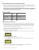
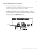
3. Strip the leads of the communication cable wires ¼ in. Insert the four wires into the screw terminals.
Make sure to match the color-coding of the four wires as shown on the screw terminal.
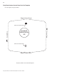
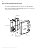
4. Feed the cable back into the wall so that the remainder left outside the wall fits behind the back plate.
Mount the control panel back plate on the wall. Secure the back plate with the two retaining screws.
5. Install two pan head retaining screws in the back plate holes. Tighten the two screws to secure the
back plate on the wall.
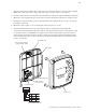
6. Mount the control panel cover over back plate and snap in place to secure.
7. After the EasyTouch load center is powered up the indoor control panel will automatically
synchronize system information from the outdoor control panel then the indoor control panel is ready
for operation. Note: If “Unit Mismatch” display on the indoor control panel you have the choice to
download the system image from the outdoor control panel or upload system information from the
indoor control panel to the outdoor control panel. For more information about synchronizing control
panels, see page 60.
Screw terminal pin-outs
Screw terminals
1DNGKLB
2TD-NRG
3TD+LEY
4V51DER
Front cover
Back plate
Mounting hole
Hole in house wall for
communication cable
Mounting hole
Snap on front
cover here first