
Data Sheet

001052 © NXP B.V. 2007. All rights reserved.
Product data sheet Rev. 5.2 — 15 January 2007 7 of 17
NXP Semiconductors
MF1 IC S50
Functional specification
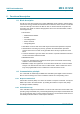
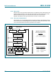
6.5 RF interface
The RF-interface is according to the standard for contactless smart cards ISO/IEC
14443A.
The carrier field from the RWD is always present (with short pauses when transmitting),
because it is used for the power supply of the card.
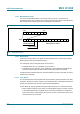
For both directions of data communication there is only one start bit at the beginning of
each frame. Each byte is transmitted with a parity bit (odd parity) at the end. The LSB of
the byte with the lowest address of the selected block is transmitted first. The maximum
frame length is 163 bits (16 data bytes + 2 CRC bytes = 16 * 9 + 2 * 9 + 1 start bit).
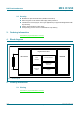
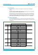
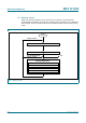
6.6 Memory organization
The 1024 x 8 bit EEPROM memory is organized in 16 sectors with 4 blocks of 16 bytes
each. In the erased state the EEPROM cells are read as a logical “0”, in the written state
as a logical “1”.
Fig 4. Memory organization
0 Data
1 Data
2 Data
Sector Block
1
Byte Number within a Block
Description
3 5 7 9 11 13
15 3 Sector Trailer 15
0 Data
2 Data
1 Data
14 3 Sector Trailer 14
0 Data
2 Data
1 Data
0 3 Sector Trailer 0
2 Data
1 Data
0 2 4 6 8 10 12 14 15
Key A Access Bits Key B
Key A Access Bits Key B
: :
: :
: :
1 3 Sector Trailer 1
Key A Access Bits Key B
0 Manufacturer Block
Key A Access Bits Key B