
Data Sheet


Fully Integrated, Hall Effect-Based Linear Current Sensor IC
with
2.1 kVRMS Isolation and a Low-Resistance Current Conductor
ACS712
12
Allegro MicroSystems, LLC
115 Northeast Cutoff
Worcester, Massachusetts 01615-0036 U.S.A.
1.508.853.5000; www.allegromicro.com
+
–
IP+
IP+
IP–
IP–
I
P
7
5
5
8
+5 V
U1
LMV7235
VIOUT
V
OUT
GND
6
2
4
4
1
1
2
3
3
FILTER
VCC
ACS712
D1
1N914
R2
100 kΩ
R1
33 kΩ
R
PU
100 kΩ
Fault
C
BYP
0.1 µF
C
F
1 nF
+
–
IP+
IP+
IP–
IP–
7
5
8
+5 V
U1
LT1178
Q1
2N7002
VIOUT
V
OUT
V
PEAK
V
RESE
T
GND
6
2
4
1
3
D1
1N914
VCC
ACS712
R4
10 kΩ
R1
1 MΩ
R2
33 kΩ
R
F
10 kΩ
R3
330 kΩ
C
BYP
0.1 µF
C1
0.1 µF
C
OUT
0.1 µF
C
F
1 nF
C2
0.1 µF
FILTER
I
P
IP+
IP+
IP–
IP–
I
P
7
5
8
+5 V
D1
1N4448W
VIOUT
V
OUT
GND
6
2
4
1
3
FILTER
VCC
ACS712
R1
10 kΩ
C
BYP
0.1 µF
R
F
2 kΩ
C
F
1 nF
C1
A-to-D
Converter
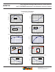
Typical Applications
Application 5. 10 A Overcurrent Fault Latch. Fault threshold set by R1 and
R2. This circuit latches an overcurrent fault and holds it until the 5 V rail is
powered down.
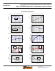
Application 2. Peak Detecting Circuit
Application 4. Rectified Output. 3.3 V scaling and rectification application
for A-to-D converters. Replaces current transformer solutions with simpler
ACS circuit. C1 is a function of the load resistance and filtering desired.
R1 can be omitted if the full range is desired.
+
–
IP+
IP+
IP–
IP–
I
P
7
5
5
8
+5 V
LM321
VIOUT
V
OUT
GND
6
2
4
1
1
4
2
3
3
FILTER
VCC
ACS712
R2
100 kΩ
R1
100 kΩ
R3
3.3 kΩ
C
BYP
0.1 µF
C
F
0.01 µF
C1
1000 pF
R
F
1 kΩ
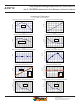
Application 3. This configuration increases gain to 610 mV/A
(tested using the ACS712ELC-05A).