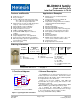
MLX90614 family Single and Dual Zone Infra Red Thermometer in TO-39 Features and Benefits Applications Examples High precision non-contact temperature measurements Thermal Comfort sensor for Mobile Air Conditioning control system Temperature sensing element for residential, commercial and industrial building air conditioning Windshield defogging Automotive blind angle detection Industrial temperature control of moving parts Temperature control in printers and copiers Home appliances with temperature contr
MLX90614 family Single and Dual Zone Infra Red Thermometer in TO-39 General description (continued) The MLX90614 is built from 2 chips developed and manufactured by Melexis: The Infra Red thermopile detector MLX81101 The signal conditioning ASSP MLX90302, specially designed to process the output of IR sensor. The device is available in an industry standard TO-39 package.
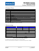
MLX90614 family Single and Dual Zone Infra Red Thermometer in TO-39 3 Table of Contents 1 Functional diagram ............................................................................................................................................................................ 1 2 General Description ........................................................................................................................................................................... 1 3 Table of Contents ...........
MLX90614 family Single and Dual Zone Infra Red Thermometer in TO-39 4 Glossary of Terms PTAT POR HFO DSP FIR IIR IR PWM DC FOV SDA,SCL Ta To ESD EMC ASSP TBD Proportional To Absolute Temperature sensor (package temperature) Power On Reset High Frequency Oscillator (RC type) Digital Signal Processing Finite Impulse Response. Digital filter Infinite Impulse Response.
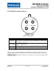
MLX90614 family Single and Dual Zone Infra Red Thermometer in TO-39 6 Pin definitions and descriptions 4 - VSS 3 - VDD 1 - SCL / Vz 2 - SDA / PWM Bottom view Figure 2: Pin description Pin Name SCL / Vz SDA / PWM Function Serial clock input for 2 wire communications protocol. 5.7V zener is available at this pin for connection of external bipolar transistor to MLX90614Axx to supply the device from external 8 …16V source. Digital input / output.
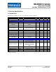
MLX90614 family Single and Dual Zone Infra Red Thermometer in TO-39 7 Electrical Specifications 7.1 MLX90614Axx All parameters are valid for TA = 25 ˚C, VDD =5V (unless otherwise specified) Parameter Symbol External supply V DD Supply current Test Conditions Min Typ Max Units 4.5 5 5.5 V Supplies IDD No load 1.3 2 mA Supply current (programming) IDDpr No load, erase/write EEPROM operations 1.5 2.5 mA Zener voltage Vz Iz = 75…1000 A (Ta=room) 5.5 5.7 5.
MLX90614 family Single and Dual Zone Infra Red Thermometer in TO-39 Parameter Symbol Test Conditions SMBus compatible 2-wire interface Min Typ Max Units 2 Input high voltage V IH (Ta, V) Over temperature and supply 3 V Input low voltage V IL (Ta, V) Over temperature and supply 0.6 V Output low voltage VOL Over temperature and supply, Isink = 2mA 0.2 V SCL leakage ISCL, leak V SCL=4V, Ta=+85°C 30 A SDA leakage ISDA, leak V SDA=4V, Ta=+85°C 0.
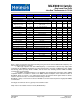
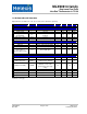
MLX90614 family Single and Dual Zone Infra Red Thermometer in TO-39 7.2 MLX90614Bxx, MLX90614Dxx All parameters are valid for TA = 25 ˚C, VDD =3V (unless otherwise specified) Parameter Symbol External supply VDD Supply current Test Conditions Min Typ Max Units 2.6 3 3.6 V Supplies IDD No load 1.3 2 mA Supply current (programming) IDDpr No load, erase / write EEPROM operations 1.5 2.5 mA Sleep mode current Isleep no load 1 2.
MLX90614 family Single and Dual Zone Infra Red Thermometer in TO-39 Parameter Symbol Test Conditions Min Typ Max Units 2 SMBus compatible 2-wire interface Input high voltage VIH(Ta,V) Over temperature and supply VDD-0.1 V Input low voltage VIL(Ta,V) Over temperature and supply 0.6 V Output low voltage VOL Over temperature and supply, Isink = 2mA 0.25 V SCL leakage ISCL,leak VSCL=3V, Ta=+85°C 20 A SDA leakage ISDA,leak VSDA=3V, Ta=+85°C 0.
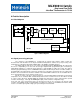
MLX90614 family Single and Dual Zone Infra Red Thermometer in TO-39 8 Detailed description 8.1 Block diagram 81101 OPA ADC DSP PWM t° STATE MACHINE Voltage Regulator 90302 Figure 3: Block diagram 8.
MLX90614 family Single and Dual Zone Infra Red Thermometer in TO-39 8.3 Block description 8.3.1 Amplifier A low noise, low offset amplifier with programmable gain is used for amplifying the IR sensor voltage. By carefully designing the input modulator and balanced input impedance, the max offset of the system is 0.5 V. 8.3.2 Supply regulator and POR The module can operate from 3 different supplies: VDD = 5V MLX90614Axx VDD = 3.
MLX90614 family Single and Dual Zone Infra Red Thermometer in TO-39 PWM period configuration: Period in extended PWM mode is twice the period in single PWM mode. In single PWM mode period is T = 1.024*P [ms], where P is the number, written in bits 15…9 PWMCTRL. Maximum period is then 131.072 ms for single and 262.144 ms for extended. These values are typical and depend on the on-chip RC oscillator absolute value.
MLX90614 family Single and Dual Zone Infra Red Thermometer in TO-39 On-chip filtering and settling time: The MLX90614 features configurable on-chip digital filters. They allow customization for speed or noise. Factory default configurations and the typical settling time and noise for the MLX90614 family are given below. Device Settling time, sec Typical noise, °C rms Spike limit MLX90614AAA, BAA, DAA MLX90614ABA, BBA MLX90614ACC, BCC MLX90614ACF, BCF MLX90614DCH, DCI, BCH, BCI 0.10 0.14 0.14 1.33 0.
MLX90614 family Single and Dual Zone Infra Red Thermometer in TO-39 8.3.4 RAM It is not possible to write into the RAM memory. It can only be read and only a limited number of RAM registers are of interest to the customer. RAM (32x17) Address Name Melexis reserved … Melexis reserved Raw data IR channel 1 Raw data IR channel 2 TA TOBJ1 TOBJ2 Melexis reserved … Melexis reserved Read access 0x00 … 0x03 0x04 0x05 0x06 0x07 Yes … Yes 0x08 0x09 … 0x1F Yes Yes … Yes Yes Yes Table 10: Ram addresses 8.
MLX90614 family Single and Dual Zone Infra Red Thermometer in TO-39 Note*: This address is readable and writable. Bit 3 should not be altered as this will cancel the factory calibration. Note**: EEPROM error signaling is implemented in automotive grade parts only. 8.4.2 Differences with the standard SMBus specification (reference [1]) There are eleven command protocols for standard SMBus interface. The MLX90614 supports only two of them.
MLX90614 family Single and Dual Zone Infra Red Thermometer in TO-39 REPEATED START, STOP, ACK, and NACK bits. The PEC is a CRC-8 with polynomial X8+X2+X1+1. The Most Significant Bit of every byte is transferred first. 8.4.3.1.1 Read Word (depending on the command – RAM or EEPROM) 1 S 7 1 Slave Address ……….. 1 8 Wr A 1 1 Command A Sr 7 1 Slave Address 1 Rd A 8 1 8 1 8 1 1 Data Byte Low A Data Byte High A PEC A P ……….. Figure 5: SMBus read word format 8.4.3.1.
MLX90614 family Single and Dual Zone Infra Red Thermometer in TO-39 The data on PWM / SDA must be changed when SCL is low (min 300ns after the falling edge of SCL). The data is fetched by both MD and SDs on the rising edge of the SCL. The recommended timing for changing data is in the middle of the period when the SCL is low. 8.4.5 Commands RAM and EEPROM can be read both with 32x16 sizes.
MLX90614 family Single and Dual Zone Infra Red Thermometer in TO-39 8.4.7 Timing specification The MLX90614 meets all the timing specifications of the SMBus [1]. The maximum frequency of the MLX90614 SMBus is 100 KHz and the minimum is 10 KHz. The specific timings in MLX90614’s SMBus are: SMBus Request ( ) is the time that the SCL should be forced low in order to switch MLX90614 from PWM mode to SMBus mode – at least 1.44ms; Timeout L is the maximum allowed time for SCL to be low during communication.
MLX90614 family Single and Dual Zone Infra Red Thermometer in TO-39 8.4.8 Sleep Mode The MLX90614 can enter in Sleep Mode via the command “Enter SLEEP mode” sent via the SMBus interface. This mode is not available for the 5V supply version.
MLX90614 family Single and Dual Zone Infra Red Thermometer in TO-39 8.4.9 MLX90614 SMBus specific remarks The auxiliary functions of the SCL pin (zener diode) add undershoot to the clock pulse (5V devices only) as shown in the picture below (see Figure 13). This undershoot is caused by the transient response of the on-chip synthesized Zener diode. Typical duration of undershoot is approximately 15 s. An increased reactance of the SCL line is likely to increase this effect.
MLX90614 family Single and Dual Zone Infra Red Thermometer in TO-39 8.5 PWM The MLX90614 can be read via PWM or SMBus compatible interface. Selection of PWM output is done in EEPROM configuration (factory default is SMBus). PWM output has two programmable formats, single and dual data transmission, providing single wire reading of two temperatures (dual zone object or object and ambient). The PWM period is derived from the on-chip oscillator and is programmable.
MLX90614 family Single and Dual Zone Infra Red Thermometer in TO-39 8.5.1 Single PWM format In single PWM output mode the settings for PWM1 data only are used. The temperature reading can be calculated from the signal timing as: 2t2 T TOUT TO _ MAX TO _ MIN TO _ MIN where Tmin and Tmax are the corresponding rescale coefficients in EEPROM for the selected temperature output (Ta, object temperature range is valid for both Tobj1 and Tobj2 as specified in the previous table) and T is the PWM period.
MLX90614 family Single and Dual Zone Infra Red Thermometer in TO-39 8.5.2 Extended PWM format The PWM format for extended PWM is shown in Figure 16. Note that with bits DUAL[5:1]>0x00 each period will be outputted 2N+1 times, where N is the decimal value of the number written in DUAL[5:1] (DUAL[5:1] =PWM control & clock [8:4] ), like shown on Figure 16.
MLX90614 family Single and Dual Zone Infra Red Thermometer in TO-39 Example: (see Figure 17 above): Configuration: Sensor1 = Ta, Sensor2 = Tobj1 Config Reg[5:4] = 00b, 0C TA _ MAX 60 C TA _ RANGE _ H EEPROM TA _ RANGE EEPROM ,0 x03 TO _ MIN 0C TO _ MAX 50 C 64 TA _ max 100 38.2 0 x3C 153.4375 153d 0 x99 0 x993C 100 TO _ min TO _ MAX EEPROM ,0 x00 59.6875 60d 64 TA _ RANGE _ H : TA _ RANGE _ L TO _ MIN EEPROM ,0 x01 38.
MLX90614 family Single and Dual Zone Infra Red Thermometer in TO-39 The TRAM is the linearized Tobj, 16-bit (0x0000…0xFFFF, 0x0000 for -273.15°C and 0xFFFF for +382.2°C) and the result is a 10-bit word, in which 0x000 corresponds to ToMIN[°C], 0x3FF corresponds to ToMAX[°C] and 1LSB corresponds to ToMAX ToMIN [°C].
MLX90614 family Single and Dual Zone Infra Red Thermometer in TO-39 8.6 Switching Between PWM / Thermal relay and SMBus communication 8.6.1 PWM is enabled The diagram below illustrates the way of switching to SMBus if PWM / Thermal Relay is enabled (factory programmed POR default for MLX90614 is SMBus, PWM disabled). Note that the SCL pin needs to be kept high in order to use PWM. tREQ>1.44ms SCL PWM/SDA Start PWM mode SMBus mode Stop Figure 18: Switching from PWM mode to SMBus 8.6.
MLX90614 family Single and Dual Zone Infra Red Thermometer in TO-39 8.7 Computation of ambient and object temperatures The IR sensor consists of serial connected thermo-couples with cold junctions placed at thick chip substrate and hot junctions, placed over thin membrane. The IR radiation absorbed from the membrane heats (or cools) it.
MLX90614 family Single and Dual Zone Infra Red Thermometer in TO-39 8.7.3 Calculation flow The measurement, calculation and linearization are held by core, which executes a program form ROM. After POR the chip is initialized with calibration data from EEPROM. During this phase the number of IR sensors is selected and it is decided which temperature sensor will be used. Measurements, compensation and linearization routines run in a closed loop afterwards.
MLX90614 family 3 TA Offset meas OSTa= meas(NTos) IR Offset meas OSIR= meas(NIRos) IR1 meas IR1D= meas(N IR) IR2 meas IR2D= meas(N IR) filtering TOS= IIR(LTos ,OSTa) filtering IROS= IIR(LIRos,OSIR) Offset comp IR1Dcomp= IR1D- IROS Offset comp IR2Dcomp= IR2D- IROS TA meas TDATA= meas(NTa) Gain drift IRGm= meas(NIRg) Gain comp IR1Dg= IR1Dcomp*KG Gain comp IR2Dg= IR2Dcomp*KG Offset comp TDATAcomp= TDATA-TOS Offset comp IRGcomp= IRGm- IROS filtering IR1D= IIR(LIR,IR1Dg) filtering IR2D= IIR(LIR,I
MLX90614 family Single and Dual Zone Infra Red Thermometer in TO-39 8.8 Thermal relay The MLX90614 can be configured to behave as a thermo relay with programmable threshold and hysteresis on the PWM/SDA pin. The input for the comparator unit of the relay is the object temperature from sensor 1 The output of the MLX90614 is NOT a relay driver but a logical output which should be connected to a relay driver if necessary. The output driver is one and the same for PWM and Thermal relay.
MLX90614 family Single and Dual Zone Infra Red Thermometer in TO-39 9 Unique Features The MLX90614 is a ready-to use low-cost non contact thermometer provided from Melexis with output data linearly dependent on the object temperature with high accuracy and extended resolution. The high thermal stability of the MLX90614-xCx make this part highly suited in applications where secondary heat sources can heat up the sensor.
MLX90614 family Single and Dual Zone Infra Red Thermometer in TO-39 10 Performance Graphs 10.1 Temperature accuracy of the MLX90614 10.1.1 Standard accuracy All accuracy specifications apply under settled isothermal conditions only. Furthermore, the accuracy is only valid if the object fills the FOV of the sensor completely. 380 To,oC ± 4 oC 300 240 ± 4 oC ± 3 oC 180 ± 4 oC ± 3 oC ± 2 oC ± 2 oC ± 2 oC ± 3 oC ± 2 oC ± 1 oC ± 1 oC ± 2 oC ± 2 oC ± 1 oC ± 0.
MLX90614 family Single and Dual Zone Infra Red Thermometer in TO-39 10.1.2 Medical accuracy A version of the MLX90614 with accuracy suited for medical applications is available. The accuracy in the range Ta 16°C…40°C and To 22°C…40°C is shown in diagram below. The accuracy for the rest of the temperature ranges is the same as in previous diagram. Medical accuracy specification is only available for the MLX90614Dxx versions. To, °C 40 38 ± 0.3°C ± 0.2°C 36 30 ± 0.
MLX90614 family Single and Dual Zone Infra Red Thermometer in TO-39 dependence comes from the ambient temperature it is the same for all type of devices regardless of FOV and optics used and it directly translates in the same compensation for object temperature. The typical VDD dependence of the ambient and object temperature is 0.6°C/V. Typical Ta=f(VDD) dependance 0.50 Sensor1 Sensor2 0.40 Sensor3 0.30 Sensor4 Sensor5 Ta error, DegC 0.20 Sensor6 0.10 Sensor7 0.00 -0.10 Sensor8 2.2 2.4 2.
MLX90614 family Single and Dual Zone Infra Red Thermometer in TO-39 10.
MLX90614 family Single and Dual Zone Infra Red Thermometer in TO-39 1.00 0.75 0.50 0.25 Angle, Deg 0.00 -80° -60° -40° -20° 0° 20° 40° 60° 80° Figure 29: Typical FOV of MLX90614xBA Figure 30: Identification of zone 1&2 relative to alignment tab 1.00 0.75 0.50 0.25 Angle, De g 0.
MLX90614 family Single and Dual Zone Infra Red Thermometer in TO-39 1.00 0.75 0.50 0.25 Angle, Deg 0.00 -80° -60° -40° -20° 0° 20° 40° 60° 80° Figure 32: Typical FOV of MLX90614xCF 1.00 0.75 0.50 0.25 0.
MLX90614 family Single and Dual Zone Infra Red Thermometer in TO-39 1.00 0.75 0.50 0.25 0.
MLX90614 family Single and Dual Zone Infra Red Thermometer in TO-39 11 Applications Information 11.1 Use of the MLX90614 thermometer in SMBus configuration +3.3V R1 R2 2 PWM SDA 3 C1 U2 0.1uF SMBus SCL 1 Vz Vdd Vss 4 U1 MCU Vdd SDA SCL GND MLX90614Bxx Figure 35: MLX90614 SMBus connection Figure 35 shows the connection of a MLX90614 to a SMBus with 3.3V power supply.
MLX90614 family Single and Dual Zone Infra Red Thermometer in TO-39 11.3 PWM output operation Using the PWM output mode of the MLX90614 is very simple, as shown in Figure 37. J1 1 SCL Vz Vdd P WM 2 SDA PWM GND U1 MLX90614 Vdd 3 C1 CON1 Vss 0.1uF Figure 37: Connection of MLX90614 for PWM output mode The PWM mode is free-running after POR when configured in EEPROM. The SCL pin must be forced high for PWM mode operation (can be shorted to VDD pin).
MLX90614 family Single and Dual Zone Infra Red Thermometer in TO-39 The MLX90614 can be configured in EEPROM to operate as a thermal relay. A non contact freezing or boiling prevention with 1 mA quiescent current can be built with two components only – the MLX90614 and a capacitor. The PWM / SDA pin can be programmed as a push-pull or open drain NMOS, which can trigger an external device, such as a relay (refer to electrical specifications for load capability), buzzer, RF transmitter or a LED.
MLX90614 family Single and Dual Zone Infra Red Thermometer in TO-39 12 Application Comments Significant contamination at the optical input side (sensor filter) might cause unknown additional filtering/distortion of the optical signal and therefore result in unspecified errors. IR sensors are inherently susceptible to errors caused by thermal gradients.
MLX90614 family Single and Dual Zone Infra Red Thermometer in TO-39 power dissipation. In case of using the MLX90614Axx internal Zener voltage feature, the regulating external transistor should also not cause heating of the TO39 package. High capacitive load on a PWM line will result in significant charging currents from the power supply, bypassing the capacitor and therefore causing EMC, noise, level degradation and power dissipation problems.
MLX90614 family Single and Dual Zone Infra Red Thermometer in TO-39 13 Standard information regarding manufacturability of Melexis products with different soldering processes Our products are classified and qualified regarding soldering technology, solderability and moisture sensitivity level according to following test methods: Wave Soldering THD’s (Through Hole Devices) EIA/JEDEC JESD22-B106 and EN60749-15 Resistance to soldering temperature for through-hole mounted devices Iron Soldering THD’s (Through
MLX90614 family Single and Dual Zone Infra Red Thermometer in TO-39 15 FAQ When I measure aluminum and plastic parts settled at the same conditions I get significant errors on aluminum. Why? Different materials have different emissivity. A typical value for aluminum (roughly polished) is 0.18 and for plastics values of 0.84…0.95 are typical.
MLX90614 family Single and Dual Zone Infra Red Thermometer in TO-39 sensor package and the sensor die. This is real optical signal that can not be segregated from the target IR signal and will add errors to the measured temperature. Thermal gradients with impact of that kind are likely to appear during transient conditions.
MLX90614 family Single and Dual Zone Infra Red Thermometer in TO-39 16 Package Information 16.1 MLX90614xxA The MLX90614 is packaged in an industry standard TO39 can. Figure 41: MLX90614xxA package Note: All dimensions are in mm 16.
MLX90614 family Single and Dual Zone Infra Red Thermometer in TO-39 16.3 MLX90614xCF Figure 43: MLX90614xCF package 16.
MLX90614 family Single and Dual Zone Infra Red Thermometer in TO-39 16.5 MLX90614xCI Figure 45: MLX90614xCI package 16.6 Part marking The MLX90614 is laser marked with 10 symbols. First 3 letters define device version (AAA, BCC, etc), and the last 7 are the lot number. Example: “ACC9307308” – MLX90614ACC from lot 9307308. 16.7 Operating and storage humidity range Operating and storage humidity range is defined as 85% non condensing humidity.
MLX90614 family Single and Dual Zone Infra Red Thermometer in TO-39 17 Table of figures Figure 1: Typical application schematics........................................................................................................... 1 Figure 2: Pin description ................................................................................................................................... 5 Figure 3: Block diagram..........................................................................................
MLX90614 family Single and Dual Zone Infra Red Thermometer in TO-39 18 References [1] System Management Bus (SMBus) Specification Version 2.0 August 3, 2000 SBS Implementers Forum Copyright . 1994, 1995, 1998, 2000 Duracell, Inc., Energizer Power Systems, Inc., Fujitsu, Ltd., Intel Corporation, Linear Technology Inc., Maxim Integrated Products, Mitsubishi Electric Semiconductor Company, PowerSmart, Inc., Toshiba Battery Co. Ltd., Unitrode Corporation, USAR Systems, Inc.
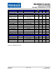
MLX90614 family Single and Dual Zone Infra Red Thermometer in TO-39 Revisions Table ! " ! # $ & * "% '( ) ! + # $ " + , - ! . * % *1 ! ,6 ( $ . . %! . 2>! / * $ 2 / '( ) 2 3 4 5 " '( ) " 8 " 9;%< # $ ! , 9$ :! " % 9 6 7 = = 6 = = " " 0 , ( $ 6 7 9$ :! ; * . ' 0 '( ) ! %$ " 6 $ ( 9 ( , " 4 % 2 3 4 55 % '( ) ( $ 2 3 4 5' 1 ! 5 % 2 3 4 5' 5 6 ! 6 9$ :! % '( ) 2 3 4 5' # $ , 6 9 3 , " " 0 6 9$ :! " 0 .