
Data Sheet

MLX90614 family
Single and Dual Zone
Infra Red Thermometer in TO-39
3901090614 Page 23 of 52 Data Sheet
Rev 008 February 28, 2013
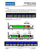
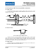
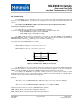
8.5.2 Extended PWM format
The PWM format for extended PWM is shown in Figure 16. Note that with bits DUAL[5:1]>0x00 each
period will be outputted 2N+1 times, where N is the decimal value of the number written in DUAL[5:1]
(DUAL[5:1] =PWM control & clock [8:4] ), like shown on Figure 16.
Figure 16: Extended PWM format with DUAL [5:1] = 01h (2 repetitions for each data)
The temperature transmitted in Data 1 field can be calculated using the following equation:
111
2
1
4
MINMINMAXOUT
TTT
T
t
T
For Data 2 field the equation is:
222
5
2
4
MINMINMAXOUT
TTT
T
t
T
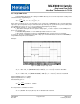
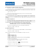
Time bands are: t
1
=0.0625 x T (Start1), t
3
=0.125 x T and t
4
=0.5625 x T (Start2 = Start1 + Valida_data1
+ error_band1 + stop1 + start2). As shown in Figure 13, in extended PWM format the period is twice the period
for the single PWM format. All equations provided herein are given for the single PWM period T. The EEPROM
Error band signaling will be 43.75% duty cycle for Data1 and 93.75% for Data2.
Note: EEPROM error signaling is implemented in automotive grade parts only.
t3
t1 t2
Start
0
T
1
16
TT
8
16
T
15
16
t=16.875ms
T=100ms (PWM = 10Hz)
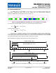
t1 t2
Start
0
T
1
16
TT
8
16
T
15
16
t=73.125ms
T=100ms (PWM = 10Hz)
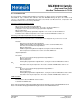
Extended PWM mode sensor 1
Extended PWM mode sensor 2
Figure 17: Example: Extended PWM mode readings – sensor 1 above and sensor 2 bellow