
User`s manual

3 - 25 3 - 25
MELSEC-Q
3 SPECIFICATIONS
Device No. Signal Name Description
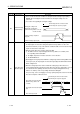
XC
Offset/gain
change
completed flag
1
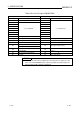
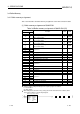
(1) This signal is used as an interlock condition to turn ON/OFF the offset/gain change
request (YC) when the offset/gain value is changed.
(2) Refer to Section 4.6 for the offset/gain setting.
Performed by the A/D converter module
Performed by the sequence program
Offset/gain change completed flag
(XC)
Offset/gain change request (YC)
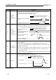
XD
Maximum
value/minimum
value reset
completed flag
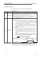
(1) This signal turns ON when the maximum value/minimum value stored at any of the
buffer memory addresses 30 to 37, 62 to 77 (Un\G30 to Un\G37, Un\G62 to Un\G77) is
reset when the Maximum value/minimum value reset request (YD) turns ON.
Maximum value/minimum value
reset completed flag (XD)
Maximum and minimum values
storage area
Buffer memory addresses 30 to 37,
62 to 77 (Un\G30 to Un\G37,
Un\G62 to Un\G77)
Maximum value/minimum value
reset request (YD)
Performed by the A/D converter module
Performed by the sequence program
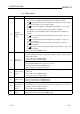
XE
A/D conversion
completed flag
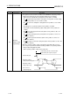
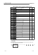
(1) This turns ON when conversion for all of the channels that are conversion enabled has
been completed.
(2)
1
When the external supply power to the Q62AD-DGH switches OFF, the A/D
conversion completed flag turns OFF, the digital output values are held as previously,
and A/D conversions stop.
When the external supply power switches ON, A/D conversions resume, and as soon as
all conversion-enabled channels have completed conversions, the A/D conversion
completed flag turns ON.
The processing, such as averaging processing or primary delay filter, starts from the first
time after resumption of A/D conversion.
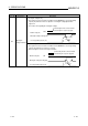
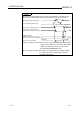
XF Error flag
(1) The error flag turns ON when a write error occurs.
(2) To clear the error code, set the error clear request (YF) to ON.
The error code is read during this interval.
Error flag (XF)
Error clear request (YF)
Performed by the A/D converter module
Performed by the sequence program
1: Q62AD-DGH only