
Owner's manual


Document No.
9100-127-1383-99 Rev B
Release Date: 10/7/2010
_____________________________________________________________________
_____________________________________________________________________________
Dialight Corporation 1501 Route 34 South Farmingdale NJ 07727
Tel: 732.919.3119 Fax: 732.751.5778 Web: www.dialight.com
Page 11 of 25
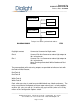
DIAGRAM SHOWING HOW TO SYNCHRONIZE FLASH RATES
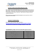
Day/Night contact Connect to Common for Night mode
Dim 0 Connect Dim 0 to Common to reduce light output to
30% of maximum
Dim 1 Connect Dim 1 to Common to reduce light output to
10% of maximum
Note: Dimming affects both White Strobe and Red
Beacon
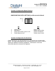
Two uncommitted solid-state relay outputs are provided to indicate a fault with
the Red or White Beacon;
Red Fault A
Red Fault B
White Fault A
White Fault B
Each solid state relay is rated for up to 600V/40mA max, 20mA continuous. The
relays can either be configured to close or open when there is a fault condition,
or pulse (fail safe, at a rate of 1 Hz with a duty cycle of 50%) when all is OK by
means of the Configuration Options switch.
Sync Out
Sync In
Sync In
To Sync In of other synchronized strobes
Master Strobe
Slave Strobe