
Owner's manual


Document No.
9100-127-1383-99 Rev B
Release Date: 10/7/2010
_____________________________________________________________________
_____________________________________________________________________________
Dialight Corporation 1501 Route 34 South Farmingdale NJ 07727
Tel: 732.919.3119 Fax: 732.751.5778 Web: www.dialight.com
Page 20 of 25
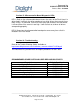
Status
Status information can be read from the microcontroller board using the following
protocol:
Master transmission
Byte Value
0 ‘S’
1 ‘R’
2 ‘D’
Slave response
Byte Value
0 ‘S’
1 ‘R’
2 ‘D’
3 Product identification, should read 0x06 for the single level FAA strobe
4 Firmware version
5 Number of white LED drivers
6 Number of faulty strings on white driver 1, if present
7 Number of faulty strings on white driver 2, if present
8 Unused
9 Red driver status: 0 if good, 1 if current is low, 2 if current is high
10 Status array, bits defined as follows:
0) 1 if unit is locked to an external sync signal, 0 if not
1) 1 if unit is receiving a 1PPM signal, 0 if not
2:3) Current dimming mode: 0 indicates 100%, 1 indicates 30%, 2 or 3
indicates 10%
4) 1 if unit is in day mode, 0 if in night mode
5) 1 if unit is set for red night mode, 0 if set for white night mode
6) 1 if unit is set for normal night flash pattern, 0 if set for WRED night
flash pattern
7) 1 if red is in steady burning mode, 0 if in flashing mode
11 Red driver voltage control feedback level
12 Red driver current sense feedback
13 Red driver voltage control adjustment level
14 Fault monitor voltage in white driver 1
15 Fault monitor voltage in white driver 2
16 Unused
17 1 if white fault alarm is active, 0 if inactive
18 1 if red fault alarm is active, 0 if inactive
19:20
100ms interval timer value, in 4us increments. In 1PPM mode, this is
adjusted to match timing with the sync signal
21 8 bit checksum, computed over bytes 3 to 20