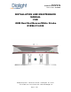
Document No. 9100-127-1354-99 Rev B Release date: 10/7/2010 INSTALLATION AND MAINTENANCE MANUAL FOR OEM Dual Red Beacon/White Strobe D1RW-C13-008 Dialight Corporation 1501 Route 34 South Farmingdale NJ 07727 Tel: 732.919.3119 Fax: 732.751.5778 Web: www.dialight.
Document No.
Document No. 9100-127-1354-99 Rev B Release Date: 10/7/2010 _____________________________________________________________________ Section 1: Overview The Dialight OEM Dual Red Beacon White Strobe Driver and Flash Head is designed to be incorporated into Medium Intensity L865 systems for the lighting of radio towers, wind generators and other obstructions to aerial navigation, as specified by the FAA and FCC. This design uses LED technology for light output both from the Beacon and White Strobe.
Document No.
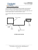
Document No. 9100-127-1354-99 Rev B Release Date: 10/7/2010 _____________________________________________________________________ Section 2: Installation and Wiring The Driver module should be mounted inside a grounded, metal enclosure to provide environmental, electromagnetic interference and safety protection. For safety, an interlock switch should be fitted to the Controller cabinet door such that when opened, power is disconnected from the system.
Document No. 9100-127-1354-99 Rev B Release Date: 10/7/2010 _____________________________________________________________________ POWER SUPPLY DIN RAIL TERMINAL CONNECTION Section 3: Flash Head Cable Connections Two conductors are required for the Red Beacon and six for the White Strobe, so eight conductors are required in total.
Document No. 9100-127-1354-99 Rev B Release Date: 10/7/2010 _____________________________________________________________________ Note: 1: If conductor thickness is reduced the maximum permissible distance between Flash Head and power supply will be reduced. 2: For maximum immunity to the effects of radiated interference and lightning, the cable from the Control Box to Power Supply Cabinet must be shielded with the shield bonded to ground at both ends.
Document No. 9100-127-1354-99 Rev B Release Date: 10/7/2010 _____________________________________________________________________ Section 4: System Installation Recommendations for EMC and Lightning Immunity 1: Electrically bond the shield of the Flash Head cable to ground at both ends. Make 360-degree ground connections around the braid or foil (avoid pigtails).
Document No. 9100-127-1354-99 Rev B Release Date: 10/7/2010 _____________________________________________________________________ Section 5: Ferrites Ferrites act to increase the inductance of a conductor and can be effective at reducing or eliminating RF or lightning immunity problems. Some Ferrites are already included in this model, both inside the Flash Head and in the Power Supply as part of lightning protection and RF immunity on the Flash Head cabling.
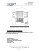
Document No. 9100-127-1354-99 Rev B Release Date: 10/7/2010 _____________________________________________________________________ MICROCONTROLLER BOARD (POWER SUPPLY) Section 7: Control Inputs Each input is active when the input terminal is connected to the negative of the supply input (Common). Input/Output Sync Input Synchronizes both White Strobe and Red Beacon. When held steady (connected to Common) the Red Beacon burns constant, and the White Strobe flashes at 40FPM.
Document No.
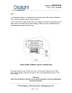
Document No. 9100-127-1354-99 Rev B Release Date: 10/7/2010 _____________________________________________________________________ Section 8: Configuration Option Switches CONFIGURATION SWITCH SETTINGS (on Microcontroller Board) 1 2 3 4 ON ON 1. 2. 3. 4.
Document No. 9100-127-1354-99 Rev B Release Date: 10/7/2010 _____________________________________________________________________ Section 10: Mounting the Flash Head Dialight recommends the installation of one or more lightning rods near the installed Flash Head. The lightning rods should extend a minimum of three feet above the height of the Flash Head. The Flash Head is mounted to the tower pedestal utilizing customer supplied ½” hardware.
Document No. 9100-127-1354-99 Rev B Release Date: 10/7/2010 _____________________________________________________________________ Section 12: Capacitor Voltage Indication Safety Warning This unit holds a number of large capacitors for storage of the energy required during the Strobe’s flash duration. These capacitors may be charged with voltages up to 185Vdc. Associated with each capacitor is a red indicator LED. When lit, this indicates the capacitor voltage is 50V or higher.
Document No. 9100-127-1354-99 Rev B Release Date: 10/7/2010 _____________________________________________________________________ Section 15: Microcontroller Board Diagnostic LEDs LED 1 (Red) on the microcontroller board shows the status of the Flash Head. In white mode, it will flash the driver number of any white drivers that currently have faulty strings. In red mode, it will flash once every two seconds if the red current is low and twice if the current is too high.
Document No. 9100-127-1354-99 Rev B Release Date: 10/7/2010 _____________________________________________________________________ Section 17: 100-240Vac Operated Systems When it is required to operate the system from a 100-240V mains supply, an additional AC to 48VDC power supply is required. It is recommended that this supply be rated for at least 120W output. If the system is to comply with FAA 150/5345-43F, certain details of this standard should be considered when choosing the power supply… Section 3.
Document No. 9100-127-1354-99 Rev B Release Date: 10/7/2010 _____________________________________________________________________ Section 18: Serial Port Specification Overview The serial port on the microcontroller is accessible through the J7 connector located on the microcontroller board. It can be used to configure the strobe unit, monitor it for status information, or provide override capability for the external control signals.
Document No. 9100-127-1354-99 Rev B Release Date: 10/7/2010 _____________________________________________________________________ Configuration Configuration information can be read or written to the microcontroller board using the following protocol. Note that changing these parameters can cause the unit to no longer be compliant with FAA or ICAO regulations.
Document No. 9100-127-1354-99 Rev B Release Date: 10/7/2010 _____________________________________________________________________ 36 8 bit checksum, computed over bytes 3 to 35 Write Command Master transmission Byte Value 0 ‘C’ 1 ‘W’ 2 ‘R’ 3 Number of white LED drivers 4 Number of faulty strings accepted before an alarm is signaled 5 Interval between white flashes, 0.
Document No.
Document No. 9100-127-1354-99 Rev B Release Date: 10/7/2010 _____________________________________________________________________ Override Override information can be written to the microcontroller board using the following protocol: Master transmission Byte Value 0 ‘O’ 1 ‘W’ 2 ‘R’ 3 Override mode array. These bits are only applied if the Enable bit (bit 0) is high and ignored otherwise.
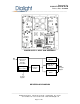
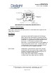
Document No. 9100-127-1354-99 Rev B Release Date: 10/7/2010 _____________________________________________________________________ POWER SUPPLY HEAT SINK ASSEMBLY AND FLASH HEAD DIMENSIONS _____________________________________________________________________________ Dialight Corporation 1501 Route 34 South Farmingdale NJ 07727 Tel: 732.919.3119 Fax: 732.751.5778 Web: www.dialight.
Document No. 9100-127-1354-99 Rev B Release Date: 10/7/2010 _____________________________________________________________________ Section 19: Specifications Operating Temperature Range -40°C to +55°C Power Supply Supply voltage: 48Vdc +/-10% Reverse polarity protected Power requirement; 90W nominal at 48V with white strobe in day mode at 40FPM and 550ft of 20AWG cable Red beacon power requirement nominally 25W when steady burning Maximum flash rate 40 FPM Dimensions - 12 x 12.
Document No. 9100-127-1354-99 Rev B Release Date: 10/7/2010 _____________________________________________________________________ REVISION HISTORY REV ECO No. DRN CKD APP QA CM DATE A B ---2138 JC SA KH KH GB GB RL RL JB JB 06/01/10 10/07/10 _____________________________________________________________________________ Dialight Corporation 1501 Route 34 South Farmingdale NJ 07727 Tel: 732.919.3119 Fax: 732.751.5778 Web: www.dialight.
Document No. 9100-127-1354-99 Rev B Release Date: 10/7/2010 _____________________________________________________________________ Section 20: Commissioning Checklist All items on checklist must be completed correctly to ensure the system functions properly and reliably. Complete and Sign below. □ □ Check that all cables, wires and connectors are connected securely in accordance with Section 2 of the Installation Manual.