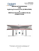
Document No. 9100-127-1560-99 Rev B Release Date: 10/10/2011 _____________________________________________________________________ INSTALLATION MANUAL FOR Lightning Protection Kit (D1RW-LPK08) In OEM Dual Red Beacon/White Strobe D1RW-C13-008 Dialight Corporation 1501 Route 34 South Farmingdale NJ 07727 Tel: 732.919.3119 Fax: 732.751.5778 Web: www.dialight.
Document No. 9100-127-1560-99 Rev B Release Date: 10/10/2011 _____________________________________________________________________ Contents Page Section 1: Overview ------------------------------------------------------------------------------3 Section 2: System Block Diagram-----------------------------------------------------------3 Section 3: Instructions --------------------------------------------------------------------------4 Dialight Corporation 1501 Route 34 South Farmingdale NJ 07727 Tel: 732.
Document No. 9100-127-1560-99 Rev B Release Date: 10/10/2011 _____________________________________________________________________ Section 1: Overview The Lightning Protection Kit (D1RW-LPK08) has been designed to further protect the Flash Head and Power Supply from transients and surges caused by direct and indirect lightning strikes. The Lightning Protection Kit consists of a lightning/surge protection board, means for properly grounding the cables and Lightning Protection Kit.
Document No. 9100-127-1560-99 Rev B Release Date: 10/10/2011 _____________________________________________________________________ Section 3: Instructions Step 1. Shut down the system and wait 1 min. for the capacitors to discharge. Step 2. Locate and remove the lid of the Lightning Protection Kit using a screw driver. Dialight Corporation 1501 Route 34 South Farmingdale NJ 07727 Tel: 732.919.3119 Fax: 732.751.5778 Web: www.dialight.
Document No. 9100-127-1560-99 Rev B Release Date: 10/10/2011 _____________________________________________________________________ Step 3. Keeping in mind that this Lightning Protection Kit should be close to the power supply so the grounding wire can reach the power supply box or chassis, cut the multi-way conductor wire that goes from the Flash Head to the power supply as shown below. Dialight Corporation 1501 Route 34 South Farmingdale NJ 07727 Tel: 732.919.3119 Fax: 732.751.5778 Web: www.dialight.
Document No. 9100-127-1560-99 Rev B Release Date: 10/10/2011 _____________________________________________________________________ Step 4. Measure roughly 8 inches of the cable. Start with the tower side. Step 5. Using a knife/ razor, carefully cut the protective cover of the wire, ensuring not to damage the wires and insulating foil inside. DO NOT CUT OFF ANY WIRE, BARE WIRE and/or FOIL. Step 6. Separate the Drain Wire (Bare wire) from the rest of the bundle.
Document No. 9100-127-1560-99 Rev B Release Date: 10/10/2011 _____________________________________________________________________ Step 7. If yellow fiber material is present, expose the yellow fiber material and remove by cutting. Be careful not to damage the wires or shielding foil. Step 8. Measure roughly 1½ - 2 inches of the foil from the protective wire cover and cut the foil as shown below. Ensure that the foil shield is wrapped around the cable and the silver foil side is facing out. Step 9.
Document No. 9100-127-1560-99 Rev B Release Date: 10/10/2011 _____________________________________________________________________ Step 10. Insert the wires and cable through the cable gland nut as shown below. Do not tighten the Gland nuts yet. Step 11. Connect the Wires to J2 “To Tower” of the Lightning Protection Board following the label “To Flash Head” for the colors as shown below. Using a small screwdriver to press in the tabs of each terminal will help ease the process of connecting the wires.
Document No. 9100-127-1560-99 Rev B Release Date: 10/10/2011 _____________________________________________________________________ Step 12. Repeat steps 4 – 9, this time using the cable on the Power supply side. Step 13. Insert the wires and cable through the cable gland nut as shown below. Do not tighten the Gland nuts yet. Step 14. Connect the Wires to J1 “From Power Supply” of the Lightning Protection Board following the label “From Power Supply” for the colors as shown below.
Document No. 9100-127-1560-99 Rev B Release Date: 10/10/2011 _____________________________________________________________________ Step 15. Ensure that the wire colors on both sides of the board match, as shown below. Step 16. Remove the wing nut and clamping washer as shown below. Dialight Corporation 1501 Route 34 South Farmingdale NJ 07727 Tel: 732.919.3119 Fax: 732.751.5778 Web: www.dialight.
Document No. 9100-127-1560-99 Rev B Release Date: 10/10/2011 _____________________________________________________________________ Step 17. Adjust the two cables so the foil on both cables are next to the stud. Step 18. Place clamping washer and tighten wing nut as shown below. Step 19. Tighten the cable gland nuts for the incoming cables into the box to roughly 20 in/lbs. A correct tight seal will prevent moisture from entering the box.
Document No. 9100-127-1560-99 Rev B Release Date: 10/10/2011 _____________________________________________________________________ Step 20. Tie the two drain (Bare) wires to the grounding stud as shown below. Cut off excess wire to prevent accidental short circuits. Step 21. If Grey and White wires are present, strip wires as shown below. Group all Grey and White wires together and secure them to the grounding stud between the two washers as shown below.
Document No. 9100-127-1560-99 Rev B Release Date: 10/10/2011 _____________________________________________________________________ Step 22. Tuck in the wires neatly so the lid does not close on top of the wires as shown below. Take care not to break any of the components or wires. Step 23. Final assembly should look like below. Place lid and ensure no wires are caught underneath and tighten screws to 20 in/lbs. A correct, tight seal will prevent moisture from entering the box.
Document No. 9100-127-1560-99 Rev B Release Date: 10/10/2011 _____________________________________________________________________ Step 24. Ground the Ground wire of the Lightning Protection Kit to the chassis of the power supply. Note that there are multiple options and below is just a few possible locations to ground the ground cable to. Dialight Corporation 1501 Route 34 South Farmingdale NJ 07727 Tel: 732.919.3119 Fax: 732.751.5778 Web: www.dialight.
Document No. 9100-127-1560-99 Rev B Release Date: 10/10/2011 _____________________________________________________________________ REVISION HISTORY REV ECO No. DRN CKD APP QA CM DATE A B 4717 4869 JC JC SA SA AR AR RL RL JB JB 09/22/11 10/10/11 Dialight Corporation 1501 Route 34 South Farmingdale NJ 07727 Tel: 732.919.3119 Fax: 732.751.5778 Web: www.dialight.