Document No. 9100-127-1556-99 Rev A October 19, 2011 _____________________________________________________________________ INSTALLATION AND MAINTENANCE MANUAL FOR P/N: D264-A54-001 24-48Vdc FLASHING RED BEACON _____________________________________________________________________________ Dialight Corporation 1501 Route 34 South Farmingdale NJ 07727 Tel: 732.919.3119 Fax:732.751.5778 Web: www.dialight.
Document No. 9100-127-1556-99 Rev A October 19, 2011 _____________________________________________________________________ Contents Page List of Figures and Tables…………………………………………………………2 Reference Drawings ……………………………………………………………….2 Section 1: Overview ……………………………………………………………….3 Section 2: Wiring and Mounting…………………………………………………. 4 Section 3: Operation and Checkout……………………………………………….6 Section 4: Beacon Theory of Operation…………………………………………...6 Section 5: Maintenance and Troubleshooting…………………. ………………...
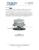
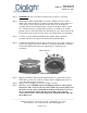
Document No. 9100-127-1556-99 Rev A October 19, 2011 _____________________________________________________________________ Section 1: Overview The Dialight Flashing Red Beacon is designed for the lighting of structures that pose a risk to aerial navigation, as specified by the FAA, ICAO and Transport Canada. The D-264 Flashing Red Beacon as shown in Figure 1, (hereafter referred to as the Beacon) is pre-wired with a power cable and operates from a nominal 24-48Vdc.
Document No. 9100-127-1556-99 Rev A October 19, 2011 _____________________________________________________________________ Section 2: Wiring and Mounting Warning: Remove power from all wiring and circuitry before installing or working on the Beacon. Wiring the Beacon The Beacon is supplied with a power cable pre-wired to the internal electronics to facilitate installation. The only connection required is 24-48Vdc power. The ground wire must be connected for proper operation and protection of the Beacon.
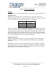
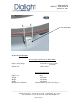
Document No. 9100-127-1556-99 Rev A October 19, 2011 _____________________________________________________________________ Figure 2 Beacon - Bottom View _____________________________________________________________________________ Dialight Corporation 1501 Route 34 South Farmingdale NJ 07727 Tel: 732.919.3119 Fax:732.751.5778 Web: www.dialight.
Document No. 9100-127-1556-99 Rev A October 19, 2011 _____________________________________________________________________ Section 3: Operation and Checkout Prior to installation, it is recommended that the unit be tested to ensure no damage was incurred during shipping. This is accomplished by applying power to the input power cable described in section 2. Visual verification of the functioning of the Beacon will indicate proper performance. Upon completion of the Checkout, the installation may proceed.
Document No. 9100-127-1556-99 Rev A October 19, 2011 _____________________________________________________________________ 4.1 Lightning Protection The Beacon incorporates protection against voltage surges (as induced by nearby lightning strikes) by means of Gas Discharge Tubes (GDT’s). Section 5: Maintenance and Troubleshooting No regularly scheduled maintenance is required for the Beacon.
Document No. 9100-127-1556-99 Rev A October 19, 2011 _____________________________________________________________________ Repair and Replacement Refer to Table 1 for troubleshooting procedures.
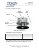
Document No. 9100-127-1556-99 Rev A October 19, 2011 _____________________________________________________________________ Step 1 WARNING: Power to the Beacon must be removed prior to servicing. Step 2 The Dome Assembly (D264-2005) is secured to the Beacon base by three latches. One of the latches has a locking screw that must be removed before it can be undone. Undo all three latches located on the base of the Beacon assembly. The Dome assembly lanyard is secured to the Beacon Base support bolt.
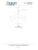
Document No. 9100-127-1556-99 Rev A October 19, 2011 _____________________________________________________________________ Cast Latch Pad Section 6: Specifications Power Supply Specifications (D264-9004) Input Voltage Range Input Power 24-48VDC (reverse polarity protected) 17W nominal Beacon Specifications Light Color Weight Height Width Bolt Hold down Pattern Red 30 Pounds 12.6 Inches 15.0 Inches Standard Pattern provided (See Fig.
Document No. 9100-127-1556-99 Rev A October 19, 2011 _____________________________________________________________________ Section 7: Regulatory Compliance and Certifications 7.1 ETL Certified to: Federal Aviation Administration (FAA): AC No. (150/5345-43F). Section 8: How to Obtain Warranty Service Refer to www.dialight.com _____________________________________________________________________________ Dialight Corporation 1501 Route 34 South Farmingdale NJ 07727 Tel: 732.919.3119 Fax:732.751.
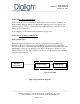
Document No. 9100-127-1556-99 Rev A October 19, 2011 ______________________________________________________________________ BEACON WIRING DIAGRAM - (Black) + (White) Power Supply Ground (Green) +Red LED Module -Black Dialight Corporation 1501 Route 34 South Farmingdale NJ 07727 Tel: 732.919.3119 Fax:732.751.5778 Web: www.dialight.
Document No. 9100-127-1556-99 Rev A October 19, 2011 _____________________________________________________________________ REVISION HISTORY REV A ECO No. DATE ----- DRN CKD APP QA CM SA KH AR RL 10/26/11 _____________________________________________________________________________ Dialight Corporation 1501 Route 34 South Farmingdale NJ 07727 Tel: 732.919.3119 Fax:732.751.5778 Web: www.dialight.