Document No. 9100-127-1733-99 Rev A June 19, 2013 _____________________________________________________________________ INSTALLATION AND MAINTENANCE MANUAL FOR P/N: D564-A13-001 120/240VAC, 50/60 Hz, L864 RED MEDIUM INTENSITY BEACON _____________________________________________________________________________ Dialight Corporation 1501 Route 34 South Farmingdale NJ 07727 Tel: 732.919.3119 Fax: 732.751.5778 Web: www.dialight.
Document No. 9100-127-1733-99 Rev A June 19, 2013 _____________________________________________________________________ Contents Page List of Figures and Tables .................................................................................2 Reference Drawings ...........................................................................................2 Section 1: Overview............................................................................................3 Section 2: Wiring and Mounting .........
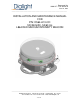
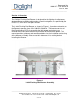
Document No. 9100-127-1733-99 Rev A June 19, 2013 _____________________________________________________________________ Section 1: Overview The Dialight Flashing Red Beacon is designed for the lighting of radio towers, wind generators and other obstructions to aerial navigation, as specified by the FAA, FCC, ICAO and Transport Canada. The L-864 Flashing Red Beacon as shown in Figure 1, (hereafter referred to as the Beacon) operates from 120 / 240VAC 50/60 Hz.
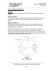
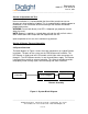
Document No. 9100-127-1733-99 Rev A June 19, 2013 _____________________________________________________________________ Section 2: Wiring and Mounting Warning: Remove power from all wiring and circuitry before installing or working on the Beacon. Wiring the Beacon The Beacon only requires a connection to 120 / 240 VAC, 50/60 Hz power. The ground wire must be connected for proper operation and protection of the Beacon.
Document No. 9100-127-1733-99 Rev A June 19, 2013 _____________________________________________________________________ Section 3: Operation and Test Prior to installation, it is recommended that the unit be tested to ensure no damage was incurred during shipping. This is accomplished by applying power to the beacon. Visual verification of the functioning of the Beacon will indicate proper performance. WARNING: Do not look directly in to LED’s. Adequate eye protection should always be used.
Document No. 9100-127-1733-99 Rev A June 19, 2013 _____________________________________________________________________ 4.1 Lightning Protection The Beacon incorporates protection against voltage surges (as induced by nearby lightning strikes for example) by means of a multi stage protection circuit utilizing the latest in arresting protective components Section 5: Maintenance and Troubleshooting No regularly scheduled maintenance is required for the Beacon.
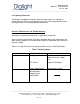
Document No. 9100-127-1733-99 Rev A June 19, 2013 _____________________________________________________________________ Repair and Replacement Refer to Table 1 for troubleshooting procedures.
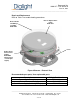
Document No. 9100-127-1733-99 Rev A June 19, 2013 _____________________________________________________________________ NOTE: The only parts that are serviceable on the Beacon are the Replacement Lamp and Power Supply. Procedure for Installing the Replacement Lamp Step 1 WARNING: Power to the Beacon must be removed prior to servicing. Step 2 Unclamp the two latches holding the lamp down. Step 3 Rotate the lamp back to its open position.
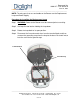
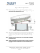
Document No. 9100-127-1733-99 Rev A June 19, 2013 _____________________________________________________________________ Figure 5 – Beacon in Open Position Step 5 Rotate the lamp downwards to approximately 10 degrees from the closed position. The key should line up with the keyway on the hinge and allow for the lamp to be pulled off of its pins. Figure 6 – Lamp Install/Removal Position Step 6 Slide the new lamp onto the pins to line it up.
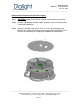
Document No. 9100-127-1733-99 Rev A June 19, 2013 _____________________________________________________________________ Replacement Procedure for the Power Supply Step 1 WARNING: Power to the Beacon must be removed prior to servicing. Step 2 Unclip 3 tabs holding the dome down and place it out of the way (dome is tethered to pedestal). Step 3 Remove 3 Phillips head screws (8-32 x ¼ inch) and accompanying lockwashers holding the Aluminum cover plate down and place it out of the way.
Document No. 9100-127-1733-99 Rev A June 19, 2013 _____________________________________________________________________ Step 4 Cut the Black/White AC wires as close to PCB as possible ensuring ferrite remains unaffected. Step 5 Cut the Red/Black output wires as close to PCB as possible. _____________________________________________________________________________ Dialight Corporation 1501 Route 34 South Farmingdale NJ 07727 Tel: 732.919.3119 Fax: 732.751.5778 Web: www.dialight.
Document No. 9100-127-1733-99 Rev A June 19, 2013 _____________________________________________________________________ Step 6 Remove 4 Phillips head screws (8-32 x ¼ inch) and accompanying lockwashers holding the power supply down. Remove the existing power supply. Be careful not to misplace the hardware. Step 7 Install the NEW potted power supply in same orientation as the existing supply using 4 Phillips head screws (8-32 x ¼ inch) and lockwashers.
Document No. 9100-127-1733-99 Rev A June 19, 2013 _____________________________________________________________________ Step 9 Re-connect output and AC wires to the new supply using wire nuts or another suitable connection. Step 10 Apply power to ensure the beacon lights up correctly. Section 6: Specifications Power Supply Specifications (D564-9000) Input Voltage Range Nominal Input Power Power Factor ATHD 120-240VAC at 50/60Hz 19W (steady burn) >0.
Document No. 9100-127-1733-99 Rev A June 19, 2013 _____________________________________________________________________ Beacon Wiring Diagram Live (Black) Neutral (White) Power Supply +Red LED Module Ground (Green) -Black REVISION HISTORY REV ECO No. DRN CKD APP QA CM DATE A ---- SA DW JP RL JN 6-19-13 _____________________________________________________________________________ Dialight Corporation 1501 Route 34 South Farmingdale NJ 07727 Tel: 732.919.3119 Fax: 732.751.5778 Web: www.