Document No. 9100-127-1438-99 Rev A March 31, 2011 _____________________________________________________________________ INSTALLATION AND MAINTENANCE MANUAL FOR P/N: D464B13001 120/240VAC, 50/60 Hz, CIDII L864 RED MEDIUM INTENSITY BEACON _____________________________________________________________________________ Dialight Corporation 1501 Route 34 South Farmingdale NJ 07727 Tel: 732.919.3119 Fax: 732.751.5778 Web: www.dialight.
Document No. 9100-127-1438-99 Rev A March 31, 2011 _____________________________________________________________________ Contents Page List of Figures and Tables .................................................................................2 Reference Drawings ...........................................................................................2 Section 1: Overview............................................................................................3 Section 2: Wiring and Mounting ........
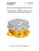
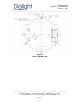
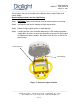
Document No. 9100-127-1438-99 Rev A March 31, 2011 _____________________________________________________________________ Section 1: Overview The Dialight Flashing Red Beacon is designed for the lighting of flare stacks, chimneys, offshore oil platforms and other obstructions to aerial navigation, as specified by the FAA, FCC, ICAO and Transport Canada. The L-864 Flashing Red Beacon as shown in Figure 1, (hereafter referred to as the Beacon) operates from 120 / 240VAC 50/60 Hz.
Document No. 9100-127-1438-99 Rev A March 31, 2011 _____________________________________________________________________ Section 2: Wiring and Mounting Warning: Remove power from all wiring and circuitry before installing or working on the Beacon. To avoid explosion: • Make sure the supply voltage is the same as the rated luminaire voltage. • Do not install where the marked operating temperatures exceed the ignition temperature of the hazardous atmosphere.
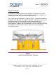
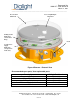
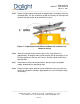
Document No. 9100-127-1438-99 Rev A March 31, 2011 _____________________________________________________________________ Figure 2 Base - Bottom View _____________________________________________________________________________ Dialight Corporation 1501 Route 34 South Farmingdale NJ 07727 Tel: 732.919.3119 Fax: 732.751.5778 Web: www.dialight.
Document No. 9100-127-1438-99 Rev A March 31, 2011 _____________________________________________________________________ Section 3: Operation and Test Prior to installation, it is recommended that the unit be tested to ensure no damage was incurred during shipping. This is accomplished by applying power to the beacon. Visual verification of the functioning of the Beacon will indicate proper performance. Upon completion of this test, the installation may proceed. Section 4: Beacon Theory of Operation 4.
Document No. 9100-127-1438-99 Rev A March 31, 2011 _____________________________________________________________________ 4.1 Lightning Protection The Beacon incorporates protection against voltage surges (as induced by nearby lightning strikes for example) by means of an MOV (metal oxide varistor) and Gas Discharge Tube (GDT) arrangement. Section 5: Maintenance and Troubleshooting No regularly scheduled maintenance is required for the Beacon.
Document No.
Document No. 9100-127-1438-99 Rev A March 31, 2011 _____________________________________________________________________ The only parts that are serviceable on the Beacon are the Light Engine and Power Supply. Replacement procedure for the Light Engine Step 1 WARNING: Power to the Beacon must be removed prior to servicing. Step 2 Unclamp the two latches holding the light engine down. Step 3 Rotate the light engine back to its open position.
Document No. 9100-127-1438-99 Rev A March 31, 2011 _____________________________________________________________________ Step 5 Rotate the light engine downwards to approximately 10 degrees from the closed position. The key should line up with the keyway on the hinge and allow for the light engine to be pulled off of its pins. Figure 6 – Light Engine Install/Removal (Dome and cantilever not shown for clarity) Step 6 Slide the new light engine onto the pins to line it up.
Document No. 9100-127-1438-99 Rev A March 31, 2011 _____________________________________________________________________ Section 6: Specifications Power Supply Specifications (D464-9000) Input Voltage Range Nominal Input Power Power Factor ATHD 120-240VAC at 50/60Hz 20W >0.9 <20% Beacon Specifications Light Color Weight Height Width Bolt Hold down Pattern Red 20 Pounds 8.4 Inches 15.0 Inches Standard Pattern provided (See Fig. 2) Section 7: Regulatory Compliance and Certifications 7.
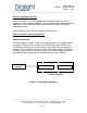
Document No. 9100-127-1438-99 Rev A March 31, 2011 _____________________________________________________________________ Beacon Wiring Diagram Live (Black) Neutral (White) Power Supply +Red LED Module Ground (Green) -Black _____________________________________________________________________________ Dialight Corporation 1501 Route 34 South Farmingdale NJ 07727 Tel: 732.919.3119 Fax: 732.751.5778 Web: www.dialight.
Document No. 9100-127-1438-99 Rev A March 31, 2011 _____________________________________________________________________ REVISION HISTORY REV ECO No. DRN CKD APP QA CM DATE A ---- SA KH JP RL JB 3/31/11 _____________________________________________________________________________ Dialight Corporation 1501 Route 34 South Farmingdale NJ 07727 Tel: 732.919.3119 Fax: 732.751.5778 Web: www.dialight.