
User's Manual
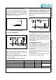
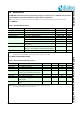


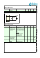


Table Of Contents
- 1.0 Connection diagram
- 2.0 Introduction
- 3.0 Specifications
- 3.1 GENERAL
- 3.2 ABSOLUTE MAXIMUM RATINGS
- 3.3 Operating Conditions
- 3.4 Digital Input/Output Pins
- 3.5 ULTRA LOW ENERGY (ULE) I/O PIN
- 3.6 SUPPLY CURRENTS
- 3.7 Analog Front End
- Table 10: Microphone amplifier
- Table 11: Microphone amplifier (Operating Condition)
- Table 12: Microphone supply voltages
- Table 13: VREFp load circuit
- Table 14: LSRp/LSRn outputs
- Table 15: LSRp/LSRn load circuits
- Table 16: PAOUTp, PAOUTn outputs
- Table 17: PAOUTp, PAOUTn outputs (Note 21)
- Table 18: PAOUTp, PAOUTn external components
- 3.8 Battery management
- 3.9 Baseband Part
- 3.10 Radio (RF) Part
- 3.11 RF Power supply
- 3.12 RF channel frequencies
- 4.0 Design guidelines
- 5.0 Notices to OEM
- 6.0 Package information
- 7.0 Revision history

SC14SPNODE SF DECT Module with integrated Antenna and FLASH
© 2012 Dialog Semiconductor B.V. 17 Jul 1, 2014 v1.6
Note 21: Clipping of the outputs occurs when the VDDPA drops and the following conditions becomes true. If CLASSD_CTRL_REG[CLASSD_CLIP]
is not equal to zero then upon a programmable number of clipping occurrences a CLASSD_INT is generated:
The software can stop clipping by reducing the gain via the GENDSP:
Clipping occurs if
Table 15: LSRp/LSRn load circuits
PARAMETER DESCRIPTION CONDITIONS MIN TYP MAX UNIT
Cp1_Rl1_inf Load capacitance see Figure 9, R
L1
= 30 pF
Cp1_Rl1_1k Load capacitance see Figure 9, R
L1
1 k 100 pF
Rl1 Load resistance 28
Cp2 Parallel load
capacitance
see Figure 10 30 pF
Cs2 Serial load capacitance 30 F
Rl2 Load resistance 600
Figure 9 Load circuit A: Dynamic loudspeaker
R
L1
C
p1
LSRp
LSRn
Figure 10 Load circuit B: Piezo loudspeaker
C
s2
LSRp
LSRn
R
L2
C
p2
Table 16: PAOUTp, PAOUTn outputs
PARAMETER DESCRIPTION CONDITIONS MIN TYP MAX UNIT
Vpa_4v Differential rms output
voltage between
PAOUTp and PAOUTn
Trimmed bandgap
input = 0 dBm0, 1 kHz
(Note 17)
Output low-pass filtered
CLASSD_VOUT = 0
0.985 Vrms
Vpa_6v As above
CLASSD_VOUT = 1
1.478 Vrms
Zload_pa_4v Speaker impedance,
connected between
PAOUTp and PAOUTn
With these values, the peak cur-
rents stays within the operating
range.
4
Zload_pa_6v 6
Table 17: PAOUTp, PAOUTn outputs (Note 21)
PARAMETER DESCRIPTION CONDITIONS MIN TYP MAX UNIT
Rout_pa Differential output
resistance between
PAOUTp and PAOUTn
See (Note 21) 1
peak LowPassFiltered PAOUTp PAOUTm–
VDDPA VSSPA–
---------------------------------------------------------------------------------------------------------------------- -
Zload
Zload Rout_pa+
-------------------------------------------