
User's Manual
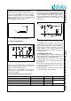
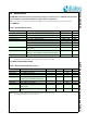


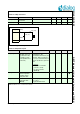


Table Of Contents
- 1.0 Connection diagram
- 2.0 Introduction
- 3.0 Specifications
- 3.1 GENERAL
- 3.2 ABSOLUTE MAXIMUM RATINGS
- 3.3 Operating Conditions
- 3.4 Digital Input/Output Pins
- 3.5 ULTRA LOW ENERGY (ULE) I/O PIN
- 3.6 SUPPLY CURRENTS
- 3.7 Analog Front End
- Table 10: Microphone amplifier
- Table 11: Microphone amplifier (Operating Condition)
- Table 12: Microphone supply voltages
- Table 13: VREFp load circuit
- Table 14: LSRp/LSRn outputs
- Table 15: LSRp/LSRn load circuits
- Table 16: PAOUTp, PAOUTn outputs
- Table 17: PAOUTp, PAOUTn outputs (Note 21)
- Table 18: PAOUTp, PAOUTn external components
- 3.8 Battery management
- 3.9 Baseband Part
- 3.10 Radio (RF) Part
- 3.11 RF Power supply
- 3.12 RF channel frequencies
- 4.0 Design guidelines
- 5.0 Notices to OEM
- 6.0 Package information
- 7.0 Revision history

SC14SPNODE SF DECT Module with integrated Antenna and FLASH
© 2012 Dialog Semiconductor B.V. 19 Jul 1, 2014 v1.6
3.8 BATTERY MANAGEMENT
3.9 BASEBAND PART
Table 19: CHARGE_CTRL pin
PARAMETER DESCRIPTION CONDITIONS MIN TYP MAX UNIT
Voh_charge_ctrl Drive capability of pin
CHARGE_CTRL
sourcing 500 A 1.6 V
Vol_charge_ctrl sinking 100 A 0.2 V
Table 20: State of charge circuit (SoC) (Operating condition)
PARAMETER DESCRIPTION CONDITIONS MIN TYP MAX UNIT
Vsocp_socn Input voltage
between SOCp and
SOCn
With the prescribed 0.1 sense
resistor this results in the usable cur-
rent range
-100 +100 mV
Figure 13 State of charge (SOC) counter accuracy
SoC_asym_err
input current
Counter ticks/s
1000 mA
100 mA
-100 mA
-1000 mA
10
0 m
A e
x
t
r
ap
ol
a
ti
o
n
A
B
SoC_sym_err: A - |B|
Table 21: Baseband specifications
PARAMETER DESCRIPTION CONDITIONS MIN TYP MAX UNIT
Fbit_uart Serial interface bit rate UART; Interface for external
microprocessor or PC
115.2 kbit/s
Fbit_flash Flash download bit rate Via UART 115.2 kbit/s
Ibat_stdby_fp Standby supply current FP application (3.3 V) 55 60 mA
Ibat_act_fp Active supply current FP application (3.3 V) 65 70 mA
Ibat_stdby_pp Standby supply current PP application (3.3 V) 4.5 6 mA
Ibat_act_pp Active supply current PP application (3.3 V) 30 40 mA