
User's Manual


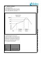


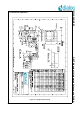
Table Of Contents
- 1.0 Connection diagram
- 2.0 Introduction
- 3.0 Specifications
- 3.1 GENERAL
- 3.2 ABSOLUTE MAXIMUM RATINGS
- 3.3 Operating Conditions
- 3.4 Digital Input/Output Pins
- 3.5 ULTRA LOW ENERGY (ULE) I/O PIN
- 3.6 SUPPLY CURRENTS
- 3.7 Analog Front End
- Table 10: Microphone amplifier
- Table 11: Microphone amplifier (Operating Condition)
- Table 12: Microphone supply voltages
- Table 13: VREFp load circuit
- Table 14: LSRp/LSRn outputs
- Table 15: LSRp/LSRn load circuits
- Table 16: PAOUTp, PAOUTn outputs
- Table 17: PAOUTp, PAOUTn outputs (Note 21)
- Table 18: PAOUTp, PAOUTn external components
- 3.8 Battery management
- 3.9 Baseband Part
- 3.10 Radio (RF) Part
- 3.11 RF Power supply
- 3.12 RF channel frequencies
- 4.0 Design guidelines
- 5.0 Notices to OEM
- 6.0 Package information
- 7.0 Revision history

SC14SPNODE SF DECT Module with integrated Antenna and FLASH
© 2012 Dialog Semiconductor B.V. 27 Jul 1, 2014 v1.6
6.0 Package information
6.1 SOLDERING PROFILE
The SC14SPNODE should be soldered using a stand-
ard reflow soldering profile and lead free solder paste
as shown below. Adjustments to the profile may be
necessary depending on process requirements.
6.2 MOISTURE SENSITIVITY LEVEL (MSL)
The MSL is an indicator for the maximum allowable
time period (floor life time) in which a moisture sensi-
tive plastic device, once removed from the dry bag, can
be exposed to an environment with a maximum tem-
perature of 30°C and a maximum relative humidity of
60% RH. before the solder reflow process.
The SC14SPNODE is qualified to MSL 3.
Figure 17 Reflow profile
MSL Level Floor Life Time
MSL 4 72 hours
MSL 3 168 hours
MSL 2A 4 weeks
MSL 2 1 year
MSL 1 Unlimited at 30°C/85%RH