
User Guide
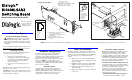

Physical Description
Pinouts for the
RJ61X Jack
8
7
6
5
4
3
2
1
12
65
34
Pinouts for the
Power Connector
1
2
3
4
5
6
PC_SENSE
-24/-70 Return
-24/-70 Return
-24 Volts
-70 Return
-24 Volts
Chassis
Ground
9
1
8
Power supply connector - Connects
to external power supply
RJ61X jacks - Connects to telephone
breakout box
Universal PCI bus connector
Audio Input Jack for music on hold
feature
6.
7.
8.
9.
8 RING 4
7 RING 3
6 RING 2
5 RING 1
4 TIP 1
3 TIP 2
2 TIP 3
1 TIP 4
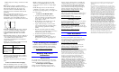
Connect Breakout Box and Power Supply
To
AC
Power
Power
Supply
DI/0408-LS-A-R2
Board
To
Telephone
Extensions
Breakout
Box
RJ61X
Cables
RJ-11
Cables
S 1-4 S 5-8 T 1-4
TO DIALOGIC PC CARD
PHONE EXTENSION
CO LINE
3
2
4
5
CT Bus connector
Green LED - Power On
Yellow LED - User Defined #1 and #2
Red LED - Out of Service
Switch SW100 - For future use
1.
2.
3.
4.
5.
6
7
To Trunk
Lines
Dialogic
®
DI0408LSAR2
Switching Board
Quick Install Card for Universal PCI
Part number 64-0039-02
Copyright © 2002-2007
Dialogic Corporation.
All Rights Reserved..
Before You Begin
Protecting the Board from Damage
Caution! All computer boards are sensitive
to electrostatic discharge (“ESD”). Handle all
static-sensitive boards and components at a static-
safe work area, and observe anti-static precautions
at all times.
NOTE: The figure shows a North American-compliant power supply cord for connecting to AC power. Use the appropriate power supply cord for your location.
If you are not familiar with ESD safety precautions, visit
http://www.dialogic.com/support/hwinstall to learn more.
Unpacking the Board
Unpack the Dialogic
®
DI0408LSAR2 Switching Board
(“board”) according to the following steps:
1. Prepare a static-safeguarded work area.
2. Carefully remove the board from the shipping
carton and anti-static packaging. Handle the
board by the edges and avoid touching the
board’s components.
3. Lay the board on the static-dissipative work
surface.
Note: Place boards in static-shielding bags when carrying
boards from station to station.
CAUTION: Do not remove the board from the anti-static
packaging until you are ready to install it. Observe proper
anti-static precautions at all times.
Hardware Configuration
The device driver, part of the system software,
assigns board identification (ID) numbers in
ascending order (beginning with 0) as it detects each
board in the system. The board identification
number is used by the system software to recognize
the board. NOTE: If you add a board to the
system, the existing board ID numbers may change,
depending upon the PCI bus and slot number where
the new board is installed.
Windows System
After the hardware and the system software are
installed, refer to the Dialogic
®
Configuration
Manager (DCM) utility to retrieve the board instance
(ID) number(s) assigned to the board(s) in your
system and see online help for more details.
Install the Hardware
With the computer on the static-safe work area and
your static-dissipative wrist strap connected to you
and the work area, ensure that the power is OFF and
disconnect all power cords from the electrical
outlets.
1. Remove the cover, select an empty PCI bus
slot and remove the slot’s retaining screw and
access coverplate.
2. Install the board into the chassis. Press firmly
until the board is securely seated in the slot.
3. Replace and tighten the retaining screw to
secure the board.
4. Replace the computer cover and reconnect the
power cords.
Set CT Bus Jumpers (optional)
The Computer Telephony bus (CT Bus) provides
communication and flexible resource sharing
among the boards connected to the bus. This
board has a CT Bus connector that complies with
the ECTF H.100 specification, and as such can be
connected to the CT Bus with a CT Bus cable.
You can connect the board to the CT Bus or use it
without the CT Bus in stand-alone mode.
• Stand-Alone Mode (CT Bus Jumpers Ignored):
For applications that do not require media sharing or
switching across the CT Bus, use the board in stand-
alone mode. No CT Bus cable is required.
In addition, you may skip the instructions in this
section when you use the board in SCbus mode
without a CT Bus master board; that is, using only
SCbus master/slave boards.
• CT Bus Mode (CT Bus Jumpers Needed): To
connect the boards to the CT Bus, set the