
IP Board Quick Installation Guide

Dialogic
®
DM/IP601-CPCI-100BT
IP Board
Quick Install Card
Part number 64-0027-02
Copyright © 2002-2007
Dialogic Corporation.
All Rights Reserved.
Before You Begin
Protecting the Board from Damage
CAUTION: All computer boards are sensitive to
electrostatic discharge (“ESD”). Handle all static-sensitive
boards and components at a static-safe work area, and
observe anti-static precautions at all times.
If you are not familiar with ESD safety precautions, visit
http://www.dialogic.com/support/hwinstall to learn more.
Unpacking the Board
Unpack the Dialogic
®
DM/IP601-CPCI-100BT board
(“board”) according to the following steps:
1. Prepare a static-safeguarded work area.
2. Carefully remove the board from the shipping
carton and anti-static packaging. Handle the
board by the edges and avoid touching the board’s
components.
3. Lay the board on the static-dissipative work
surface.
Note: Place boards in static-shielding bags when carrying
boards from station to station.
CAUTION: Do not remove the board from the anti-static
packaging until you are ready to install it. Observe proper
anti-static precautions at all times.
Installing the Hardware
NOTE: In a Windows environment, install the software
first, the hardware second, and then run the Dialogic
®
Configuration Manager (DCM) to configure the system.
1. Turn the power to the chassis OFF if you do not have a
live insertion system. If you do have live insertion
capability, the power to the chassis can remain ON.
2. Remove the chassis cover plate or open the front door.
3. Select an empty expansion bus slot.
NOTE: When power is on, the Rear I/O module should be
installed first, before the main board.
4. Install the Rear I/O module in the rear of the slot
selected in step 3. Use the slot’s board guides as you
insert the board into the chassis slot. Make sure that the
tabs on the board extractors engage the guide holes in
the chassis card cage, then lock down the board
extractors until the red locking tabs snap shut.
CAUTION
cPCI backplane pins are bent easily. Make sure that
the board is seated with hand pressure before fully
seating board. If board extractors are used to seat
the board, make sure to seat evenly.
5. Install the board in the front of the slot selected in step 3.
Use the slot’s board guides as you insert the board into
the chassis slot. Make sure that the tabs on the board
extractors engage the guide holes in the chassis card
cage, then lock down the board extractors until the red
locking tabs snap shut.
NOTE: If the power to the chassis is on, power is
automatically applied to the board, the Out of Service
LED lights briefly and then goes out, and the Power
LED goes on.
6. Tighten the retaining screws to secure the board firmly
in the chassis slot (optional).
7. Select a new slot and repeat steps 4-6 for each board you
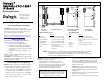
Physical Description
RED
YEL
CARR
SGNL
LOOP
RED
YEL
CARR
SGNL
LOOP
A
L
A
R
M
S
T
A
T
U
S
RED
YEL
CARR
SGNL
LOOP
RED
YEL
CARR
SGNL
LOOP
A
L
A
R
M
S
S
A
T
U
S
P5
P4
P1
Board
Extractor
POWER
Alarm
Status
LEDs
OUT OF
SERVICE
Board
Extractor
Baseboard
Daughterboard
12
34
/
P5
P2
P2
P5
J1-J4
RJ-48C Jacks
BNC Connectors
Ethernet
Interface
Connector
Ethernet
Interface
Connector
Trunk 1Trunk 1
Trunk 2
Trunk 3
Trunk 4
Faceplate Compact PCI Board T-1 and E-1 120-Ohm E-1 75-Ohm
(front view) Rear I/O Module Rear I/O Module
Compact PCI Baseboard Rear I/O Modules
Part:
Power LED
Red Alarm LEDs
Yellow Alarm LEDs
Carrier Signal LEDs
Loopback LEDs
Out of Service LED
Function:
Indicates board is powered up.
Not functional in this assembly.
Not functional in this assembly.
Not functional in this assembly.
Not functional in this assembly.
Indicates board is out of service
or in reset from host.
Part:
J1–J4
P2
P5
BNC
Connectors
Function:
Not functional in this assembly.
Telephony network interface test port
Rear I/O module connector to Compact PCI
backplane
Not functional in this assembly
P1, P4, P5
Compact PCI board connectors
to backplane.
Ethernet
Connector
Connection to Ethernet network
NOTES: Rear I/O Modules are ordered separately and are available in two different forms depending
on the type of connectors used, guided or unguided. Select a Rear I/O Module that is
compatible with your chassis type. See the PICMG 2.0 D3.0 Compact PCI Specification for
more information on guided and unguided connectors.