
Installation guide

Part number: 64-0360-01
Dialogic
®
DSI
SS7MDL440Q Network
Interface Board
Installation Guide
Copyright © 2009 Dialogic Corporation.
All rights reserved.
1. Product Description
The Dialogic® DSI SS7MDL440Q Network Interface
Board (“DSI SS7MDL440Q board” or “board”) is a
high performance, low profile, PCI Express form
factor SS7 signaling board designed for use in
telecommunications environments.
The board supports configurations of up to 124 SS7
signaling links, 4 framed HSL links, or 4 ATM cell
streams.
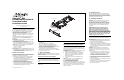
The DSI SS7MDL440Q board includes the following
components, shown in the Physical Layout
illustration:
End Bracket: Bracket supplied for both low profile
and full height installation.
Port 0 to Port 3: Four primary rate
telecommunication interface connectors that are
run-time configurable to operate as T1, E1, or J1
ports, with selectable line code and frame format.
LEDs: Each port is provided with a Green/Red bi-
color LED to indicate status:
■
Green = Line Ok
■
Red = Line Alarm
Bus Interface: The DSI SS7MDL440Q board is a 4
lane PCI Express physical form factor with a single
lane connected, which can be installed in 4, 8, or
16 lane PCI Express slots.
Additional Information
Additional information about each DSI SS7MDL440Q
board and the specifications to which it conforms is
available in the following documents:
■
The Regulatory Notices document, packed with
each DSI SS7MDL440Q board, contains safety
warnings and international and national
requirements for proper installation and operation
of telecommunications equipment.
■
Dialogic® DSI SS7MD Network Interface Board
Programmer's Manual, available at http://
www.dialogic.com/support/helpweb/signaling,
provides information about the software used with
each DSI SS7MDL440Q board, including
configuration parameters and command
descriptions.
■
The product data sheet, available at
http://www.dialogic.com/products/list.asp,
provides a functional description as well as
information about applications and configurations,
features, and technical specifications.
■
The latest software, available at http://
www.dialogic.com/support/helpweb/signaling.
■
PCI Express Base Specification Rev 1.0a, available
at http://www.pcisig.com.
2. Before You Begin
Familiarize yourself with the safety aspects and other
essential or national requirements in the Regulatory
Notices document.
Protecting the Board from Damage
CAUTION: All computer boards are sensitive to
electrostatic discharge (“ESD”). Handle all static-
sensitive boards and components at a static-safe
work area, and observe anti-static precautions at all
times.
If you are not familiar with ESD safety precautions,
visit http://www.dialogic.com/support/hwinstall to
learn more.
Unpacking the Board
CAUTION: Do not remove the board from the anti-
static packaging until you are ready to install it.
Observe proper anti-static precautions at all times.
Inspect the packaging for any signs of damage that
may have occurred during transit. In the event of
damage or missing items notify both the carrier and
the supplier immediately.
Unpack the DSI SS7MDL440Q board according to the
following steps:
1. Prepare a static-safeguarded work area.
2. Carefully remove the board from the shipping
carton and anti-static packaging. Handle the
board by the edges and avoid touching the
board’s components.
3. Lay the board on the static-dissipative work
surface.
Note: Place board in static-shielding bag when
carrying board from station to station.
3. Configuring the Board
Software configurable parameters must be set, as
described in the DSI SS7MD Network Interface Board
Programmer's Manual. These include parameters
relating to T1/E1/J1 ports, pulse shape, line code,
and frame format.
4. Choosing a Slot
For restrictions, refer to the DSI SS7MD Network
Interface Board Programmer's Manual and the host
computer documentation. Ensure that the creepage
and clearance requirements are met, as specified in
the Regulatory Notices document.
5. Installing the Board
CAUTION: These procedures assume familiarity
with the general terminology associated with
electronic equipment and with the safety practices
and regulatory compliance required for using and
modifying electronic equipment. These procedures
should be performed only by qualified technical
personnel.
WARNING! Unplug the equipment before
performing the procedures described here.
Failure to disconnect the power before you
open the chassis can result in personal injury.
Ensure that the system is disconnected from its
power source and from all telecommunications
links, networks, or modem lines whenever the
chassis cover is removed. Do not operate the
system with the cover removed.
CAUTION: Observe proper anti-static precautions at
all times while handling and installing the board.
To install the DSI SS7MDL440Q board, perform the
following steps:
1. Turn off the computer and disconnect the power
cable and network connections.
2. Remove the cover from the computer.
3. Select an empty, PCI Express slot and remove the
blanking plate (if fitted) by removing the retaining
screw at the top of the plate. Keep the blanking
plate for future use.
CAUTION: To prevent damage to the board or
computer, care should be taken to ensure correct
alignment of the connector and board guide before
final insertion.
4. The end bracket on the board may need to be
changed between either low profile or full height
to match the selected host PCI Express slot.
Instructions on how to do this are provided in
Section 6, Changing the End Bracket.
5. Using the board guides in the computer, align the
board with the slot and press the board firmly
until fully seated.
6. Secure the board using the retaining screw at the
top of the end bracket.
7. Replace the cover on the computer and reconnect
the power cable and network connections.
8. Turn on the computer.
Physical Layout
Low Profile Bracket
Port Status LEDs
Port 0
Full Height Bracket
(Optional)
Bracket Retaining Screw
Port 1
Port 2
Port 3
Bus Interface