Dialogic® DSI SS7MD Network Interface Boards Programmer’s Manual www.dialogic.
Copyright© 2009 Dialogic Corporation. All Rights Reserved. You may not reproduce this document in whole or in part without permission in writing from Dialogic Corporation at the address provided below. All contents of this document are furnished for informational use only and are subject to change without notice and do not represent a commitment on the part of Dialogic Corporation or its subsidiaries ("Dialogic"). Reasonable effort is made to ensure the accuracy of the information contained in the document.
Dialogic® DSI SS7MD Programmer’s Manual Issue 3 Contents 1 Introduction ............................................................................................................. 7 1.1 Related Information ............................................................................................ 7 2 Specification ............................................................................................................. 9 2.1 Product Identifiers .....................................................
Contents 4.9 4.10 4.11 4.8.3 Dynamic Operation .................................................................................37 4.8.4 Example Code for Building and Sending MVD_MSG_SC_LISTEN Message........37 4.8.5 Interconnecting LIUs using STREAM_XCON ................................................38 Received Message Timestamping .........................................................................39 4.9.1 Host Configuration .......................................................................
Dialogic® DSI SS7MD Programmer’s Manual Issue 3 Figures 1 2 3 4 Switch Connections...................................................................................................36 Drop and Insert........................................................................................................38 Protocol Configuration Message Sequence Diagram ..................................................... 179 Q.SAAL Configuration Message Sequence Diagram ....................................................
Contents Revision History Date Part Number Issue July 2009 05-2640-003 3 Description of thermal sensor operation added. Description May 2009 05-2640-002 2 Support for introduction of ATM termination mode and timestamping. April 2009 05-2640-001 1 Supports the first production release. Note: The current issue of this guide can be found at: http://www.dialogic.
Dialogic® DSI SS7MD Programmer’s Manual Issue 3 Chapter 1: Introduction Dialogic® DSI SS7MD Network Interface Boards are specialized T1/E1/J1 SS7 signaling boards suitable for use in PCI Express form factor systems. The boards use the common Dialogic® DSI software API to the application that enables applications to be easily ported. The boards provide a hardware platform to enable running Dialogic® DSI Protocol Stacks for the realization of Signaling System Number 7 signaling nodes.
1 Introduction 8
Dialogic® DSI SS7MD Programmer’s Manual Issue 3 Chapter 2: Specification This chapter provides information about: • • • Product Identifiers Dialogic® DSI SS7MDL4 Network Interface Board - Low Profile PCI Express Form Factor Software Licenses 9
2 Specification 2.1 Product Identifiers The Dialogic® DSI SS7MD Network Interface Board product family includes the PCI Express form factor described in the following subsections. 2.1.1 Dialogic® DSI SS7MDL4 Network Interface Board - Low Profile PCI Express Form Factor Product DSI SS7MDL4 PCI Express form factor product line includes the following: • DSI SS7MDL440Q A low profile PCI Express form factor with 4 T1/E1/J1 ports, supporting up to 124 SS7 links, up to 4 SS7 HSL links, up to 128 Q.
Dialogic® DSI SS7MD Programmer’s Manual Issue 3 Dialogic® DSI SS7MDL4 Network Interface Board - Low Profile PCI Express Form Factor 2.2 The DSI SS7MDL4 board is a x1 lane electrical, x4 lane physical, low profile PCI Express form factor, which can be installed in x4, x8, or x16 lane slots. The board is supplied with two End Brackets suitable for low profile and full height installation. Features of the DSI SS7MDL4 board are described in the following topics: • • • • • • • • • 2.2.
2 Specification which to install the board. Refer to Section 2.2.7, “Airflow Requirements” on page 13 for more information. 2.2.3 Physical Interfaces The DSI SS7MDL4 board supports the following physical interfaces: • Four T1/E1/J1/J1 digital trunk interfaces. See Section 2.2.3.1 below for more detail. 2.2.3.
Dialogic® DSI SS7MD Programmer’s Manual Issue 3 2.2.5 Visual Indicators The DSI SS7MDL4 board includes the following visual indicators: • T1/E1/J1 dual-color Green/Red status LEDs: — Green indicates a valid link — Red indicates a line alarm Note: Only the LEDs 0, 1, 2, and 3 are active (LEDs 4, 5, 6, and 7 are reserved for future use). 2.2.6 Power Requirements Power requirements are described as follows: • • 2.2.7 +12 VDC power 1.1 A typical, 1.4 A max. Power dissipation 17 W max.
2 Specification 2.2.9 Safety, EMC and Telecommunications Specifications Safety, EMC and telecommunications specification information is provided by the following: • • • Dialogic® DSI SS7MDL440Q Network Interface Board Regulatory Notices Supplied with each product and provides a full list of the specifications to which DSI SS7MDL4 board conforms. International Declaration of Conformity See http://www.dialogic.com/declarations.
Dialogic® DSI SS7MD Programmer’s Manual Issue 3 2.3 Software Licenses The DSI SS7MDL4 codefile supports different MTP2 link densities on the board. These are enabled using a Host Software License that is to be ordered at the same time as the hardware. The Host Software License licenses a specific number of link resources on the host that may be shared between boards in the same chassis.
2 Specification The following combinations of link types are available to the user: Run Mode LSL Links HSL Links ATM Links LSL Y Y Y HSL Y Y Y ATM Y Y IMA IMA Links Y Y Y Note: When using multiple link types on the same board, the run mode indicates to the board the predominant link type. Note: To change the run mode of a board, the board must be reset.
Dialogic® DSI SS7MD Programmer’s Manual Issue 3 Chapter 3: Installation This chapter contains the following topics: • • • Software Packages Software Installation for Linux Software Installation for Solaris (SPARC) 17
3 Installation 3.1 Software Packages This manual describes the installation and use of the following software: • • • 3.1.1 Development Package User Part Development Package Binary for Dialogic® DSI SS7MD Network Interface Boards Development Package Different variants of the Development Package are available for the supported operating systems.
Dialogic® DSI SS7MD Programmer’s Manual Issue 3 3.2 Software Installation for Linux The Development Package for Linux is distributed as a download from the Dialogic web site. See Section 1.1, “Related Information” on page 7. The distribution is in the form of a single compressed file called dpklnx6.Z. Installation of the software is described in more detail in the following topics: • • • • • 3.2.
3 Installation The ldconfig utility creates a symbolic link to the GCT library shared object within the install directory. For example: /opt/dpklnx: libgctlib.so.1 -> libgctlib.so.1.0.1 If the installation machine is to be used to build applications, an additional link must be created from libgctlib.so.1 to libgct.so: ln -s libgctlib.so.1 libgct.so 3.2.
Dialogic® DSI SS7MD Programmer’s Manual Issue 3 3.2.3 Support for a Large Number of DSI Messages The default Linux configuration may need to be modified to support a large number of DSI messages. 1. Edit the /etc/rc.local (or distribution-specific equivalent) file to add the following line: sysctl -w kernel.msgmnb= where is set to at least¹ the sum of the number of normal and long DSI messages allocated by gctload, multiplied by 12. For example, a system.
3 Installation ss7dpk-devel-5.08-1..rpm ss7dpk-debuginfo-5.08-1..rpm ss7dpk-kmod-5.08-1.2.6.9_34.EL..rpm Where is i386 for 32bit operation and x86_64 for 64 bit operation systems. Note: Device driver binaries, including the one for the DSI SS7MD Board, will be built as rpmbuild is run. Therefore, it is necessary for the machine on which rpmbuild is run to share the same kernel version as the machine on which the RPM packages will be installed. 3.2.5.
Dialogic® DSI SS7MD Programmer’s Manual Issue 3 3.3 Software Installation for Solaris (SPARC) Installation of the software is described in more detail in the following topics: • • • • Additional Commands Support for Larger Message Queues Removing the Development Package for Solaris Solaris Interface Name Checking The Development Package for Solaris is distributed in the form of a compressed file called dpksol64 for use with 64-bit kernels. This file can be downloaded from http://www.dialogic.
3 Installation 3.3.1 Additional Commands Customers using Solaris 10 and the DSI SS7MD Boards must perform the following additional commands after installing the package: cd/opt/DKseptel chown root ssdm chmod +s ssdm Note: The commands should be executed by a user with super-user permissions. 3.3.2 Support for Larger Message Queues The number of messages available to the system is limited by the number of kernel message headers. Attempting to use more messages may cause the system to halt.
Dialogic® DSI SS7MD Programmer’s Manual Issue 3 Chapter 4: Dialogic® DSI SS7MD Board Configuration and Operation Before attempting software configuration, you should gain an appreciation of the flexibility of the protocol stack, the run-time options that exist and the mechanisms that are used to select specific features. This section gives an overview of these options. You should also read the Software Environment Programmer’s Manual that describes the basic principles of modules and message passing.
4 Dialogic® DSI SS7MD Board Configuration and Operation 4.1 Regulatory and Geographic Considerations Certain functions of Dialogic® DSI SS7MD Boards, although implemented in hardware, have selectable options that are configured by the ss7.dc6 codefile. A user or integrator must consider the requirements of the application when choosing these settings, but must also consider any local regulatory requirements for the intended deployment location to ensure a compliant overall system.
Dialogic® DSI SS7MD Programmer’s Manual Issue 3 4.2 System Structure The Dialogic® DSI Protocol Stack software running on the board communicates with the higher level protocols running on the main CPU of the host computer. The user’s application may also be running on the host computer. See Section 4.3, “Running Host Binaries With Dialogic® DSI SS7MD Board” on page 28 for more information. The physical interface to the board uses the PCI Express bus.
4 Dialogic® DSI SS7MD Board Configuration and Operation 4.3 Running Host Binaries With Dialogic® DSI SS7MD Board The Dialogic® DSI MTP2 Layer protocol module runs on the board. The other SS7 protocol modules (MTP3, ISUP, TUP, SCCP, TCAP, MAP, INAP, and IS41) must be run on the host machine. Host protocol software is available for Linux and Solaris SPARC operating systems. For more information or to purchase, contact an authorized distributor or your account manager.
Dialogic® DSI SS7MD Programmer’s Manual Issue 3 4.4 System Configuration System configuration is handled by the gctload program that reads system configuration data from a file called system.txt. System initialization requires: • • • First, that a pool of message buffers is created for subsequent inter-process communication. Second, that a message queue is created for each process that will run and that any message redirection for modules that are running remotely is initialized.
4 Dialogic® DSI SS7MD Board Configuration and Operation NUM_MSGS 1000 * Number of standard size messages * * Optional Modules that run on the host: * * LOCAL 0x23 * ISUP module * LOCAL 0x4a * TUP module * LOCAL 0x33 * SCCP module * LOCAL 0x14 * TCAP module * LOCAL 0x22 * MTP3 module * * * Redirection of status indications: * REDIRECT 0xdf 0x2d * LIU/MTP2 status messages -> upe REDIRECT 0xef 0x2d * Other indications -> upe * * Start-up all local tasks: * FORK_PROCESS ./ssdm FORK_PROCESS .
Dialogic® DSI SS7MD Programmer’s Manual Issue 3 It is next necessary to include FORK_PROCESS commands for the modules running on the host computer. All systems require ssdm, tick and tim binaries to be run. • For Linux users, the mandatory FORK_PROCESS commands are: FORK_PROCESS FORK_PROCESS FORK_PROCESS • ./ssdm ./tim_lnx ./tick_lnx For Solaris users, the mandatory FORK_PROCESS commands are: FORK_PROCESS FORK_PROCESS FORK_PROCESS ./ssdm ./tim_sol .
4 Dialogic® DSI SS7MD Board Configuration and Operation 4.5 Protocol Configuration The Development Package contains the s7_mgt protocol configuration utility that performs initialization of all the software modules running on the signaling board. It reads the protocol configuration data from a text file, called config.txt, and provides a quick and flexible method of configuring the protocol modules without the need to write any software for that purpose. Refer to Section 4.5.
Dialogic® DSI SS7MD Programmer’s Manual Issue 3 * * ISUP parameters: * * Configure ISUP module: * ISUP_CONFIG *ISUP_CONFIG 0 0 0x1d 0x0435 4 64 * * Configure ISUP circuit groups: * ISUP_CFG_CCTGRP * *ISUP_CFG_CCTGRP 0 1 0x01 0x01 0x7fff7fff 0x001c 0 0x1d 2 0x8 0 0x00 * * * TUP parameters: * Configure TUP module: * TUP_CONFIG
4 Dialogic® DSI SS7MD Board Configuration and Operation 4.6 Monitoring The monitoring option can be used in conjunction with the SS7 Development Package for the appropriate operating system (Linux or Solaris) to realize a high-performance protocol monitor with up to 4 boards, each monitoring a certain number of links (see the table in Section 2.3.1, “Run Modes” on page 15 for details).
Dialogic® DSI SS7MD Programmer’s Manual Issue 3 4.7 ATM Monitoring The system can also be used to monitor AAL5 traffic that is running over ATM links. The following is an example config.txt configuration file to support AAL5 Monitoring: ******************************************************************************** * Example Protocol Configuration File (config.txt) for use with * Dialogic(R) DSI SS7MD Network Interface Boards.
4 Dialogic® DSI SS7MD Board Configuration and Operation 4.8 Switching Timeslots between LIUs The Dialogic DSI SS7MD Boards support multiple T1/E1/J1 Line Interface Units (LIUs). The onboard signaling processor handles the SS7 signaling timeslots, while the remaining circuits (voice or data bearer circuits) are switched to another onboard LIU for distribution to other boards. Communication between the application and the board is message-based.
Dialogic® DSI SS7MD Programmer’s Manual Issue 3 4.8.2 Static Initialization Static initialization is handled by the s7_mgt protocol configuration utility. For each T1/E1/J1 Line Interface Unit (LIU), the user should include an LIU_SC_DRIVE command in the config.txt protocol configuration file. The LIU_SC_DRIVE command has several parameters. The board_id and liu_id parameters together uniquely identify the affected LIU.
4 Dialogic® DSI SS7MD Board Configuration and Operation MSG *m; u8 *pptr; /* * Allocate a message (and fill in type, id, rsp_req & len): */ if ((m = getm(MVD_MSG_SC_LISTEN, 0, RESPONSE(OUR_MOD_ID), MVDML_SCLIS)) != 0) { pptr = get_param(m); memset(pptr, 0, m->len); /* * Enter the parameters in machine independent format: */ rpackbytes(pptr, MVDMO_SCLIS_liu_id, (u32)liu_id, MVDMS_SCLIS_liu_id); rpackbytes(pptr, MVDMO_SCLIS_timeslot, (u32)timeslot, MVDMS_SCLIS_timeslot); rpackbytes(pptr, MVDMO_SCLIS_sc_chann
Dialogic® DSI SS7MD Programmer’s Manual Issue 3 4.9 Received Message Timestamping Timestamping of received messages can be enabled for monitored links. This functionality provides a timestamp of the time a message is received by a board. Individual boards maintain time by synchronising with the host time. The following table provides details of the expected timestamp accuracy between boards, in a multi board system: Operating System 4.9.
4 Dialogic® DSI SS7MD Board Configuration and Operation 4.10 High Speed Link Operation High Speed Link (HSL) operation is supported in the following mode: • Structured mode, where the data stream is framed as for conventional SS7: — For T1, 8 bits in each of 24 timeslots are available for signalling. — For E1, timeslot 0 is used for framing and 31 timeslots are available for signaling. The implementation supports the use of both 7-bit and 12-bit sequence numbers as a run-time configuration option.
Dialogic® DSI SS7MD Programmer’s Manual Issue 3 4.11 Operation of the Thermal Sensor Thermal Protection The Dialogic® DSI SS7MDL4 Network Interface Board is a high performance, densely packed, low profile PCIe board supporting high message rates.
4 Dialogic® DSI SS7MD Board Configuration and Operation 42
Dialogic® DSI SS7MD Programmer’s Manual Issue 3 Chapter 5: Program Execution This chapter describes how to start the software and execute programs. It assumes that: • • • The software has already been installed. Refer to Chapter 3, “Installation”. The system.txt configuration file has been modified correctly. Refer to Section 4.4, “System Configuration” on page 29. The config.txt protocol configuration file has been modified correctly. Refer to Section 4.5, “Protocol Configuration” on page 32.
5 Program Execution 5.1 Program Execution Overview There are three main stages to getting a new application up and running, although the precise means of achieving this vary slightly depending upon the operating system: 1. Ensure that the device driver is installed and running. 2. Ensure that the protocol software is running on the host. 3.
Dialogic® DSI SS7MD Programmer’s Manual Issue 3 5.2 Program Execution Under Linux and Solaris Proceed as follows: 1. Ensure the device driver has been installed and the system.txt configuration file has been modified in accordance with system requirements to select the correct protocols etc. 2. Ensure that the correct codefile has been copied into the directory containing all the SS7 binaries. 3. If using the s7_mgt protocol configuration utility, ensure that the config.
5 Program Execution 46
Dialogic® DSI SS7MD Programmer’s Manual Issue 3 Chapter 6: Message Reference This section describes the individual messages that may be sent to or received from a Dialogic® DSI SS7MD Board. Some messages are sent by the user's application software, while others are sent by utility programs such as the s7_mgt protocol configuration utility. Prior to sending any message to the board, the application should call the GCT_set_instance( ) library function to select which board the message will be sent to.
6 Message Reference 6.1 DSI SS7MD Software Module IDs for DSI SS7MD Board Table 6 lists the software modules IDs (by mnemonic and value) used on the DSI SS7MD Board. Table 6. DSI SS7MD Board Software Module IDs Mnemonic 48 Value Description MGMT_TASK_ID 0x8e SS7MD Board Management Module MVD_TASK_ID 0x10 SS7MD LIU and Switch Management Module SS7_TASK_ID 0x71 MTP2 Module DVR_ALT_TASK_ID 0x61 Signaling Driver Module ATM_TASK_ID 0x31 ATM Module QSL_TASK_ID 0x41 Q.
Dialogic® DSI SS7MD Programmer’s Manual Issue 3 6.2 General Configuration Messages General configuration messages are typically issued by the s7_mgt protocol configuration utility, in which case they need not, and should not, be generated by any user application software.
6 Message Reference Parameters The SSD_MSG_RESET message includes the following parameters: • • mgmt_id The module ID of the management module to which SSD should send board status indications. num_boards The maximum number of boards that ssd is required to manage. This should not exceed 4. 6.2.2 SSD_MSG_RST_BOARD – Board Reset Request Synopsis Reset a single board and download a codefile.
Dialogic® DSI SS7MD Programmer’s Manual Issue 3 • run_mode The protocols to be run. The following table shows the permitted values and their meaning. Value Run Mode Protocols Selected to Run on the Board 34 LSL MTP2 Low Speed Links 35 HSL MTP2 High Speed Links 36 ATM ATM links 37 IMA Inverse Multiplexed ATM links The following combinations of link types are available to the user.
6 Message Reference 6.2.3 SSD_MSG_BOARD_INFO – Board Information Request Synopsis Message used to retrieve information about the DSI SS7MD Board. Format MESSAGE HEADER Field Name Meaning type SSD_MSG_BOARD_INFO (0x7689) id board_id src Sending module ID dst SSD_module_ID rsp_req Used to request a confirmation. Hclass 0 Status 0 err_info 0 Len 38 PARAMETER AREA Offset Size Name 0 4 ssd_mode 4 2 board_type 6 10 Reserved. Must be set to 0.
Dialogic® DSI SS7MD Programmer’s Manual Issue 3 • • current_temp Signed 8-bit value containing the current temperature of the board within the range -128 to 127 degrees Celsius. max_temp Signed 8-bit value containing the maximum temperature the board has reached since SSDM was last started. Value is within the range -128 to 127 degrees Celsius. 6.2.
6 Message Reference — Bit 15 is set to 1 for diagnostics purposes to cause the results of board configuration to be passed to the host. When set, all confirmation messages generated internally on the board during the configuration sequence are sent to the 0xdf module ID on the host. — All other bits are reserved for future use and should be set to 0. • l1_flags Level 1 flags with the following bit significance: — Bit 0 controls the layer 1 clock reference source.
Dialogic® DSI SS7MD Programmer’s Manual Issue 3 Configure the LSL timeslot rate: • • • • • l1_resource_id Layer 1 (logical) resource identifier. data_rate Used for setting the link operation. The following table shows the permitted values and their meaning. Value Data Rate 0 64 kbits/s 1 56 kbits/s 2 48 kbits/s link_source Configure the signaling source. Set to 0 for DSI SS7MD Board. link_stream Signaling stream.
6 Message Reference 6.2.6 MGT_MSG_L1_END – Layer 1 Configuration End Synopsis Message sent to a board to remove an existing layer 1 link that was previously configured by sending an MGT_MSG_L1_CONFIG message. Format MESSAGE HEADER Field Name Meaning type MGT_MSG_L1_END (0x7f18) id 0 src Sending module's module ID dst MGMT_module_ID rsp_req Used to request a confirmation. hclass 0 status 0 err_info 0 len 4 PARAMETER AREA Offset Size 0 2 2 2 Name Reserved. Must be set to 0.
Dialogic® DSI SS7MD Programmer’s Manual Issue 3 Parameters The MGT_MSG_NTP_CONFIG message includes the following parameters: • • • enable Set to 1 to enable timestamping, 0 to disable timestamping. poll_interval Set to 4. ntp_management_id Set to 0x20.
6 Message Reference 6.3 Hardware Control Messages Hardware control messages are used to control various hardware devices on the board, including the T1/E1/ J1 Line Interface Units (LIUs), the digital cross connect switches and the clocking mode for the board. In a static configuration, these hardware blocks can be set up using the s7_mgt protocol configuration utility along with the appropriate commands in the config.txt protocol configuration file.
Dialogic® DSI SS7MD Programmer’s Manual Issue 3 6.3.1 LIU_MSG_CONFIG – LIU Configuration Request Synopsis Message sent by the application to establish the operating mode for a Line Interface Unit (LIU). Note: When using the s7_mgt protocol configuration utility, this message is generated by s7_mgt as a result of the LIU_CONFIG command. It therefore need not be generated by the user.
6 Message Reference 3 E1 120 ohm balanced interface 4 T1 (including J1) 5 E1 120 ohm balanced interface Note: The option chosen by the user must be appropriate to the actual hardware fitted; otherwise an error status is returned. • line_code The line coding technique. The following table shows the permitted values and their meanings. Value • Description 1 HDB3 (E1 only) 2 AMI 4 B8ZS (T1/J1) frame_format The frame format. The following table shows the permitted values and their meanings.
Dialogic® DSI SS7MD Programmer’s Manual Issue 3 10 • T1 long haul LB0 (-15dB) 11 Not supported. 12 T1 long haul LBO (-22.5dB) ais_gen The (initial) mode used to generate the Alarm Indication Signal (Blue alarm). The user may subsequently modify the setting of the outgoing signal using the LIU_MSG_CONTROL message. The following table shows the permitted values and their meanings.
6 Message Reference 6.3.2 LIU_MSG_CONTROL – LIU Control Request Synopsis Message sent by the application to dynamically control operation for a Line Interface Unit (LIU). Allows setting of outgoing alarms and diagnostic loopbacks. Format MESSAGE HEADER Field Name Meaning type LIU_MSG_CONTROL (0x7e35) id liu_id (in the range 0 to one less than the number of LIUs) src Sending module ID dst MVD_module_ID rsp_req Used to request a confirmation.
Dialogic® DSI SS7MD Programmer’s Manual Issue 3 • loop_mode The diagnostic loopback mode. The following table shows the permitted values and their meanings. Value • Description 0 Do not change diagnostic loopback mode 1 Disabled - remove any diagnostic loop 2 Payload loopback 3 Remote loopback 4 Local loopback prbs_gen The Pseudo Random Bit Sequence (PRBS) generation mode. The following table shows the permitted values and their meanings. Value 6.3.
6 Message Reference 6.3.4 LIU_MSG_R_CONTROL – LIU Read Control Request Synopsis Message sent by the application to read back the current Line Interface Unit (LIU) control options from the board. Format MESSAGE HEADER Field Name Meaning type LIU_MSG_R_CONTROL (0x5e38) id liu_id (in the range 0 to one less than the number of LIUs) src Sending module ID dst MVD_module_ID rsp_req Used to request a confirmation.
Dialogic® DSI SS7MD Programmer’s Manual Issue 3 The confirmation message (if requested) indicates success with a status value of 0. On receipt of the confirmation message, the operation to reset the switch is completed. 6.3.6 MVD_MSG_SC_CONNECT – Connect Request Synopsis Message sent to the board to control the switch path. Format MESSAGE HEADER Field Name Meaning type MVD_MSG_SC_CONNECT (0x7e1f) id 0 src Sending module ID dst MVD_module_ID rsp_req Used to request a confirmation.
6 Message Reference Parameters The parameters that can be included in the MVD_MSG_SC_CONNECT message depend on the requested mode.
Dialogic® DSI SS7MD Programmer’s Manual Issue 3 • • • • Value Meaning 6 Remove a duplex connection between two timeslots on the cross connect switch and one timeslot on the CPU local bus. Use the local_stream and local_slot parameters to specify both timeslots for disconnection. 8 Remove a connection between a switch timeslot and a CPU local bus timeslot. Then create a simplex connection between the same CPU local bus timeslot back to the switch timeslot.
6 Message Reference 6.3.7 MVD_MSG_SC_MULTI_CONNECT – Multiple Connect Request Synopsis Message sent to the board to control the switch to connect multiple paths. Format MESSAGE HEADER Field Name Meaning type MVD_MSG_SC_MULTI_CONNECT (0x7e19) id 0 src Sending module ID dst MVD_module_ID rsp_req May be used to request a confirmation.
Dialogic® DSI SS7MD Programmer’s Manual Issue 3 • source_st, source_ts When mode is set to 11, these parameters give the source_st and source_ts for connection to the specified local timeslots. For other modes the source_st and source_ts specify the cross connect switch stream and timeslot, respectively. 6.3.8 MVD_MSG_SC_DRIVE_LIU – LIU Switch Initialization Synopsis Sets up a static switch path through the board between a CPU local bus timeslot and a switching channel.
6 Message Reference • mode The mode of operation that controls how the switch channels are allocated. Typically, when mode is set to 1, the first timeslot connected to the switch is connected to the timeslot indicated by sc_channel and each subsequent timeslot that is connected will be connected to the next switch channel. This allows maximum utilization of channels on the switch.
Dialogic® DSI SS7MD Programmer’s Manual Issue 3 6.4 Signaling Interface Messages Signaling interface messages allow signaling links to be activated and deactivated by the user and provide a mechanism for communication between the MTP3 module and the user part module (for example, ISUP, TUP or SCCP). In many cases, the user part module is an Dialogic® DSI Protocol Stack so the user does not need to handle the MTP primitives as they pass directly between MTP3 and the user part module.
6 Message Reference 6.4.1 SS7_MSG_CONFIG – MTP2 Link Configuration Request Synopsis Message issued by management to MTP2 to configure an individual signaling link for operation. Format MESSAGE HEADER Field Name Meaning type SS7_MSG_CONFIG (0x7203) id l2_llid src Sending module ID dst MTP2_module_ID rsp_req Used to request a confirmation. Sending layer's bit set if response required.
Dialogic® DSI SS7MD Programmer’s Manual Issue 3 messages may be issued to the MTP2 module to modify timer configuration parameters however; these messages do not affect SS7 operation (that is, the power up sequence is not re-executed, but the parameters are modified). For backwards compatibility, the MTP2 module accepts messages with three different parameter area lengths: 38, 42 or 60 bytes.
6 Message Reference the loop delay in ms for 56 kbits/s operation. If set to 0, the MTP2 module assumes a value of 12800 for an HSL link, 400 otherwise. • • • • • • • rtv_attempts Reserved. Set to 0. t1, t2, t3, t4n, t4e, t5, t6, t7 Values for the protocol timers as defined in Q.703. These should be set to the number of (tick * timer_res) intervals required for the timer. The timers are checked for expiry every timer_res number of ticks. The value given for t1, t2 etc.
Dialogic® DSI SS7MD Programmer’s Manual Issue 3 Parameters The MTP_MSG_RX_IND message includes the following parameter: • • • Signaling Unit Data The SU data in binary format, excluding the Flags and Checksum. UUI User to User Information – parameter generated when operating in ATM monitoring mode only. CPI Common Part Indicator – parameter generated when operating in ATM monitoring mode only. 6.4.
6 Message Reference • seconds_fraction Binary fractions of a second. 6.4.4 API_MSG_TX_REQ – MTP2 Transmission Request Synopsis Message issued to the board by MTP3, containing an SS7 Message Signal Unit (MSU) for transmission on the specified link. Format MESSAGE HEADER FIELD NAME MEANING type API_MSG_TX_REQ (0xcf00) id l2_llid src Sending module ID dst MTP2 module ID rsp_req Sending layers bit set if response is required.
Dialogic® DSI SS7MD Programmer’s Manual Issue 3 6.4.5 GEN_MSG_MOD_IDENT – Module Identification Request Synopsis Message issued to request software version. Format MESSAGE HEADER FIELD NAME MEANING type GEN_MSG_MOD_IDENT (0x6111) id 0 src Sending module's ID dst MGMT_module_ID rsp_req Used to request a confirmation.
6 Message Reference 6.5 ATM Interface Messages ATM Interface Messages allow ATM links to be configured, activated, and deactivated by the user.
Dialogic® DSI SS7MD Programmer’s Manual Issue 3 • options Bit 0 Use ATM Forum Idle cell format rather than ITU. 1 Use VPI and VCI masks supplied rather than default masks of 0x00f (VPI) and 0x01ff 01ff 01ff 01ff 01ff 01ff 01ff 01ff 01ff 01ff 01ff 01ff 01ff 01ff 01ff 01ff (VCI) Others • • Description Reserved for future use. Must be set to 0. num_streams The maximum number of cell streams this module will be asked to simultaneously support.
6 Message Reference 6.5.2 ATM_MSG_CFG_STREAM – ATM Cell Stream Configuration Synopsis Message used to configure an ATM cell stream. Format MESSAGE HEADER FIELD NAME MEANING type ATM_MSG_CFG_STREAM (0x7261) id Cell Stream ID src Management module ID dst ATM_module_ID rsp_req Used to request a confirmation.
Dialogic® DSI SS7MD Programmer’s Manual Issue 3 • options Bit Mnemonic Description 0 ATM_CFG_OPTIONS_SCRAMBLE Enable payload scrambling 1 ATM_CFG_OPTIONS_COSET Use ATM coset in HEC calculation 2 ATM_CFG_OPTIONS_AUTOCORRECT Autocorrect invalid cells if possible 3 ATM_CFG_OPTIONS_IMA_BUNDLE Configuration describes an IMA bundle Note: Either Payload Scrambling or ATM Coset mode, or both, must be enabled for correct operation. Configurations which disable both options will be rejected.
6 Message Reference Note: Attempting to activate TDM timeslots that are not present on the underlying TDM (e.g., using a bitmap of 0xfffefffe when the TDM is configured as T1) may NOT result in the rejection of the configuration message. • • mgmt_id ID of management module for status updates. upper_stream_id Upper layer (layer 3) stream identifier – this is a logical identifier from the upper layer for the cell stream and is not board specific. 6.5.
Dialogic® DSI SS7MD Programmer’s Manual Issue 3 PARAMETER AREA OFFSET 0 SIZE 4 NAME period 4 4 rx_frames 8 4 rx_octets 12 4 rx_discard_frames 16 4 rx_errors 20 4 tx_frames 24 4 tx_octets 28 4 tx_discard_frames 32 4 tx_errors Description Sent by the user to request (and optionally reset) the statistics for the cell stream. The values returned are the totals for the links using this cell stream. The confirmation message (if requested) indicates success with a status value of 0.
6 Message Reference 6.5.5 ATM_MSG_AAL_CFG_MON_LINK – Configure AAL Monitor Link Synopsis Message used to configure a monitor link. Format MESSAGE HEADER FIELD NAME MEANING type ATM_MSG_AAL_CFG_MON_LINK (0x7264) id link_id src Sending module ID dst ATM_module_ID rsp_req Used to request a confirmation.
Dialogic® DSI SS7MD Programmer’s Manual Issue 3 • • • VPI The VPI of the AAL5 stream to be monitored. The VPI must be viable in the mask configured in the ATM_MSG_CONFIG message. VCI The VCI of the AAL5 stream to be monitored. The VCI value must be viable in the mask specified in the ATM_MSG_CONFIG message. Note: 0, 3, and 4 are reserved. mgmt_id ID of management module for status updates. Notes: The VPI/VCI combination configured here must not match the default specified for the cell stream.
6 Message Reference 6.5.7 ATM_MSG_R_AAL_LINK_STATS – Per Monitored Link Statistics Synopsis Message used to retrieve (and reset) per monitored link statistics. Format MESSAGE HEADER FIELD NAME MEANING type ATM_MSG_R_AAL_LINK_STATS (0x6266) id link_id src Sending module ID dst ATM_module_ID rsp_req Used to request a confirmation.
Dialogic® DSI SS7MD Programmer’s Manual Issue 3 6.5.8 ATM_MSG_STREAM_STATE – ATM Stream Status Indication Synopsis Primitive generated by ATM to advise management of changes to the stream state.
6 Message Reference 6.5.9 ATM_MSG_LINK_STATE – AAL Link Status Indication Synopsis Primitive generated by AAL to advise management of changes to the link state. Format MESSAGE HEADER Field Name type Meaning ATM_MSG_LINK_STATE (0x026b) id link_id src ATM Module ID dst Management Module ID rsp_req 0 hclass 0 status Stream state (see table below) err_info Timestamp len 0 Description Sent by the ATM module when an AAL link becomes active or inactive.
Dialogic® DSI SS7MD Programmer’s Manual Issue 3 6.6 Q.SAAL Module This section describes the formats of all the messages used in the non-primitive interface. The full list of management requests sent to Q.SAAL includes: • • • • • • • • • SS7_MSG_RESET - Q.SAAL Module Reset Request QSL_MSG_CFG_LINK - Configure Q.SAAL Link QSL_MSG_CFG_TIMERS - Configure Timers per Q.SAAL Link QSL_MSG_END_LINK - Remove Q.
6 Message Reference • num_links Maximum number of Q.SAAL signaling links to support on this board. This may range from 0 to one less than the maximum number of links supported depending on how many signaling links the user wishes to use. It is not necessary to always use this number of links. 6.6.2 QSL_MSG_CFG_LINK – Configure Q.SAAL Link Synopsis Message issued by management to configure an individual Q.SAAL link for operation.
Dialogic® DSI SS7MD Programmer’s Manual Issue 3 QSAAL_MSG_TIMERS messages may be issued to the Q.SAAL module to modify timer configuration parameters however; these messages do not affect Q.SAAL operation (that is, the power up sequence is not re-executed, but the parameters are modified). • link_id Identifier for this link. Note: This identifier is required to be unique only within the context of the board.
6 Message Reference • co1, co2, co3, ca1, ca2, ca3, cd1, cd2, cd3 Congestion onset, abatement and discard thresholds for use when the Multiple Congestion Thresholds mode of operation is selected. The following relationships must be true: ca1 <= co1 <= ca2 <= co2 <= ca3 <= co3 and co1 <= cd1 <= co2 <= cd2 <= co3 <= cd3. Notes: • • • The VPI/VCI combination configured here must not match the default specified for the cell stream. Once the message has been received and processed by the Q.
Dialogic® DSI SS7MD Programmer’s Manual Issue 3 Description QSAAL_MSG_CFG_LINK messages may be issued to the Q.SAAL module to modify timer configuration parameters. Otherwise default timer values will be used.
6 Message Reference 6.6.4 QSL_MSG_END_LINK – Remove Q.SAAL Link Synopsis Remove a Q.SAAL Link - only allowed when the link is in the inactive state. Message Format MESSAGE HEADER Field Name type Meaning QSL_MSG_END_LINK (0x7269) id Link ID src User Module ID dst QSL_TASK_ID rsp_req Used to request a confirmation hclass 0 status 0 err_info 0 len 0 Description Sent by the user to deactivate a link, remove its connection from the underling ATM cell stream and release its resources.
Dialogic® DSI SS7MD Programmer’s Manual Issue 3 6.6.5 SS7_MSG_TRACE_MASK – Set Trace Mask Request Synopsis Message issued to Q.
6 Message Reference • ip_evt_mask The input event trace mask. This is a 16-bit value with bits set to 1 to cause a trace message to be sent to the management module whenever a message is received by Q.SAAL. Care should be taken when tracing messages, as system throughput may be reduced. The fields in the trace mask cause the events indicated in the table below to be traced.
Dialogic® DSI SS7MD Programmer’s Manual Issue 3 6.6.6 SS7_MSG_R_STATE – Read Link State Request Synopsis Message sent to Q.
6 Message Reference 6.6.7 SS7_MSG_R_STATS – Read Link Statistics Request Synopsis Message sent to Q.SAAL module to retrieve per link statistics in same format as MTP2.
Dialogic® DSI SS7MD Programmer’s Manual Issue 3 6.6.8 MGT_MSG_QSL_EVENT – Q.SAAL "Q.791 style" Event Indication Synopsis "Q791 style" event indication generated by Q.SAAL module to advise management of protocol events. Message Format MESSAGE HEADER Field Name type Meaning MGT_MSG_QSL_EVENT (0x026c) id Link ID src QSL_TASK_ID dst Management module ID rsp_req 0 hclass 0 status 0 err_info Timestamp len 0 Description Sent by Q.SAAL module to management when an event occurs.
6 Message Reference 6.6.9 MGT_MSG_SS7_STATE – Link State Indication Synopsis Indication generated by Q.SAAL module to advise management of changes to the per-link state Message Format MESSAGE HEADER Field Name type Meaning MGT_MSG_SS7_STATE (0x0201) id Link ID src QSL_TASK_ID dst Management module ID rsp_req 0 hclass 0 status Link State (see below) err_info Timestamp len 0 Description: This primitive is used by Q.
Dialogic® DSI SS7MD Programmer’s Manual Issue 3 6.6.11 Primitives issued to MTP3-b The following primitives are supported by the Q.SAAL module. For message definitions refer to Dialogic® SS7 Protocols MTP2 Programmer's Manual.
6 Message Reference 6.7 Event Indication Messages Event indication messages are the mechanism by which protocol and software error events are reported to the application. These messages are generated asynchronously by different modules within the stack.
Dialogic® DSI SS7MD Programmer’s Manual Issue 3 6.7.2 MGT_MSG_TRACE_EV – Trace Event Indication Synopsis Message issued by a module to trace protocol events. Message Format MESSAGE HEADER Field Name Meaning type MGT_MSG_TRACE_EV (0x0003) id 0 src generating module_id dst management module id rsp_req 0 hclass 0 status 0 err_info Timestamp len 18 + length of traced data PARAMETER AREA Offset Size Name 0 1 src - hdr->src from traced message. 1 1 dst - hdr->dst from traced message.
6 Message Reference 6.7.3 SSD_MSG_STATE_IND – Board Status Indication Synopsis Message sent to the application on completion of the reset and download sequence or on detection of a board status event. Note: This message is not required when using the s7_mgt protocol configuration utility.
Dialogic® DSI SS7MD Programmer’s Manual Issue 3 6.7.4 API_MSG_CNF_IND – Configuration Completion Status Indication Synopsis Message issued by the s7_mgt protocol configuration utility on completion of initial configuration sequence. Format MESSAGE HEADER Field Name Meaning type API_MSG_CNF_IND (0x0f09) id 0 src 0xcf dst Notification module (see below) rsp_req 0 hclass 0 status completion_status (see below) err_info Reserved for future use.
6 Message Reference 6.7.5 MVD_MSG_LIU_STATUS – LIU Status Indication Synopsis Message issued by the board to provide notification of changes in LIU status. Format MESSAGE HEADER Field Name Meaning type MVD_MSG_LIU_STATUS (0x0e01) id liu_id (in the range 0 to one less than the number of LIUs) src MVD_module_ID dst MGMT_module_ID rsp_req 0 hclass 0 status liu_status (see below) err_info Reserved for future use.
Dialogic® DSI SS7MD Programmer’s Manual Issue 3 6.7.6 MGT_MSG_SS7_EVENT – MTP2 Q.791 Event Indication Synopsis Message issued by the MTP2 module to advise management of protocol events in accordance with Q.791.
6 Message Reference 6.7.7 MGT_MSG_NTP_SYNC – Timestamping Resynchronization Indication Synopsis Message sent if a significant time difference between the board and the host is detected. This message is generated only if received message timestamping is configured. See Section 4.9, “Received Message Timestamping” on page 39 for more information.
Dialogic® DSI SS7MD Programmer’s Manual Issue 3 6.8 Status Request Messages Status request messages can be used to poll the status of modules or systems running on the board. The messages in the status request category include: • • • • LIU_MSG_R_STATE - LIU Read State Request LIU_MSG_R_STATS - LIU Read Statistics Request MGT_MSG_R_BRDINFO - Read Board Info Request DVR_MSG_R_L1_STATS - Link Statistics Request 6.8.
6 Message Reference 6.8.2 LIU_MSG_R_STATS – LIU Read Statistics Request Synopsis Message used to read back performance statistics associated with a Line Interface Unit (LIU). Format MESSAGE HEADER Field Name Meaning type LIU_MSG_R_STATS (0x5e36) id liu_id (in the range 0 to one less than the number of LIUs) src Sending module ID dst MVD_module_ID rsp_req Used to request a confirmation.
Dialogic® DSI SS7MD Programmer’s Manual Issue 3 — For E1 operating modes, it is the number of errors detected in the frame alignment word. — For T1 interfaces operating in D3/D4 frame format, it is the number of framing bit errors. — For T1 interfaces operating in ESF format, it is the number of CRC6 errors.
6 Message Reference 6.8.3 MGT_MSG_R_BRDINFO – Read Board Info Request Synopsis Message used to request basic board information.
Dialogic® DSI SS7MD Programmer’s Manual Issue 3 6.8.4 DVR_MSG_R_L1_STATS – Link Statistics Request Synopsis Retrieve link statistics. Format MESSAGE HEADER Field Name Meaning type DVR_MSG_R_L1_STATS (0x6136) id l1_llid src Sending module ID dst module ID of onboard HDLC/SS7 driver rsp_req Used to request a confirmation, sending layer’s bit must be set.
6 Message Reference • • • • • 114 receiver_busy_cnt The number of times the receiver has entered the busy state as a result of the number of internal buffers falling below a set threshold. rx_frame_cnt The number of (error-free) frames received on the link, excluding any duplicate frames that are discarded as a result of the internal filtering mechanism.
Dialogic® DSI SS7MD Programmer’s Manual Issue 3 6.9 Message Summary Table The following table lists, by message type, all the messages described in this manual. Table 7. Message Summary Message Type Mnemonic Description 0x0003 MGT_MSG_TRACE_EV Trace Event Indication 0x0008 MGT_MSG_EVENT_IND Error Indication 0x0201 MGT_MSG_SS7_STATE Link State Indication 0x0202 MGT_MSG_SS7_EVENT MTP2 Q.
6 Message Reference Table 7. Message Summary (Continued) Message Type 116 Mnemonic Description 0x6214 SS7_MSG_R_STATS Read Link Statistics Request 0x6215 SS7_MSG_R_STATE Read Link State Request 0x6263 ATM_MSG_R_STREAM_STATS Per ATM Cell Stream Statistics 0x6266 ATM_MSG_R_AAL_LINK_STATS Per Monitored Link Statistics 0x6f0d MGT_MSG_R_BRDINFO Read Board Info Request 0x7200 SS7_MSG_RESET Q.
Dialogic® DSI SS7MD Programmer’s Manual Issue 3 Chapter 7: Configuration Command Reference This chapter describes the commands and parameters used in the config.txt protocol configuration file. These commands are used by the s7_mgt protocol configuration utility to perform one time configuration of the protocol stack at startup.
7 Configuration Command Reference 7.
Dialogic® DSI SS7MD Programmer’s Manual Issue 3 SS7_BOARD – Configure Dialogic® DSI SS7MD Network Interface Board 7.1.1 Synopsis Command to configure a DSI SS7MD Board in the system. Syntax SS7_BOARD Example SS7_BOARD 0 SS7MD 0x0000 ss7.
7 Configuration Command Reference • • • The logical identity of the board in the range from 0 to one less than the number of boards supported. The identifier of the T1/E1/J1 Line Interface Unit (LIU) in the range from 0 to one less than the number of LIUs. The physical interface type. The following table shows the permitted values and their meanings. Value Description 1 Disabled (used to deactivate an LIU). In this mode the LIU does not produce an output signal.
Dialogic® DSI SS7MD Programmer’s Manual Issue 3 • The build out type. The following table shows the permitted values and their meanings. Value Description 0 Setting for E1 devices 1 T1/J1 default (short haul) 8 T1/J1 long haul LBO (-0 dB) 9 T1/J1 long haul LBO (-7.5 dB) 10 T1/J1 long haul LBO (-15 dB) 12 T1/J1 long haul LBO (-22.
7 Configuration Command Reference 7.1.3 LIU_SC_DRIVE – Set Up Path Between LIU Synopsis This command is used during initialization to set up a static switch path between the Line Interface Units (LIUs) and the cross connect switch. It connects selected incoming voice timeslots from one T1/E1/J1 LIU to a sequential block of channels on the internal switch and prepares the outgoing timeslots for subsequent use by the MVD_MSG_SC_LISTEN message.
Dialogic® DSI SS7MD Programmer’s Manual Issue 3 7.1.4 SCBUS_LISTEN – Connect Switch Timeslot to LIU Timeslot Synopsis This command establishes a connection from the switch to an outgoing timeslot on the Line Interface Unit (LIU). Note: Dynamic modification of voice paths can only be performed by issuing messages directly to the board. The MVD_MSG_SC_LISTEN message is recommended for this purpose.
7 Configuration Command Reference 7.1.5 STREAM_XCON – Cross Connect Configuration Synopsis The STREAM_XCON command controls the cross connect switch on the signaling boards, enabling the crossconnection of timeslots between two Line Interface Unit (LIU) on each signaling board. The LIUs on a board are referenced by a fixed logical stream number. Note: The option 1 and parameter is not supported on DSI SS7MD Boards.
Dialogic® DSI SS7MD Programmer’s Manual Issue 3 — E1 interfaces have 32 timeslots numbered 0 to 31. Timeslot 0 is used for frame alignment and timeslot 16 is generally used for signaling or is empty. Hence the normal configuration is to cross connect timeslots 1 to 15 and 17 to 31 between the two ports on each signaling board by setting the value to 0xfffefffe. — T1/J1 interfaces have 24 timeslots, numbered 1 to 24.
7 Configuration Command Reference 7.
Dialogic® DSI SS7MD Programmer’s Manual Issue 3 7.2.1 MONITOR_LINK – Configure Link in Monitoring Mode Synopsis The MONITOR_LINK command allows the user to configure a signaling link or ATM link to operate in monitoring only mode. The command is differentiated based on the data rate parameter. Received signaling messages are passed directly to a user application without further processing.
7 Configuration Command Reference • An optional parameter to specify link parameters, required for HSL or ATM operation.
Dialogic® DSI SS7MD Programmer’s Manual Issue 3 7.3 MTP Configuration Commands The Message Transfer Part (MTP) configuration commands are: • • • • • MTP_CONFIG - Configure MTP MTP_LINKSET - Configure a Linkset MTP_LINK - Configure a Link MTP_ROUTE - Configure a Route MTP_USER_PART - Configure a Local User Part 7.3.1 MTP_CONFIG – Configure MTP Synopsis The global configuration parameters for the Message Transfer Part (MTP).
7 Configuration Command Reference set to 0, on detection of RPO, the signaling link is taken out of service and restoration commences. This bit should normally be set to 1. — Bit 20 used in conjunction with bit 9 to select point codes (see table above). — Bit 21 should be set to 1 for use in Japanese networks; otherwise it should be set to 0. All other bits are reserved for future use and should be set to 0. Note: For correct ANSI operation, bits 8, 9, 10, 11 and 18 must be set to 1.
Dialogic® DSI SS7MD Programmer’s Manual Issue 3 7.3.2 MTP_LINKSET – Configure a Linkset Synopsis Configuration of a linkset to an adjacent signaling point. Syntax MTP_LINKSET Example MTP_LINKSET 0 321 2 0x0000 456 0x8 Parameters The MTP_LINKSET command includes the following parameters: • • • • • • The logical identity of the linkset, in the range 0 to one less than the number of linksets supported.
7 Configuration Command Reference Syntax MTP HSL/LSL Links MTP_LINK
Dialogic® DSI SS7MD Programmer’s Manual Issue 3 — Bit 12 is used to select 12- or 7-bit sequence numbers for HSL only. This bit should be set for 12-bit sequence numbers, clear otherwise. — Bits 13 and 14 reserved. Set to 0. — Bit 15 is set to 1 to disable the link. This bit should be set to 0 to enable normal link operation. — All other bits are reserved for future use and should be set to 0. • An optional parameter to specify link parameters, required for HSL or ATM operation.
7 Configuration Command Reference — vpi is the Virtual Path Indicator of the signaling link within the ATM cell stream. — vci is the Virtual Channel Indicator of the signaling link within the ATM cell stream. For restrictions on the choice of VPI-VCI combinations refer to Section 6.5.1, “ATM_MSG_CONFIG” on page 78. 7.3.4 MTP_ROUTE – Configure a Route Synopsis Configuration of a route for use with one or more user parts.
Dialogic® DSI SS7MD Programmer’s Manual Issue 3 — All other bits are reserved for future use and must be set to 0. 7.3.5 MTP_USER_PART – Configure a Local User Part Synopsis Configuration of a local user part module, other than a user part which has its own configuration command in the config.txt protocol configuration file. Syntax MTP_USER_PART Example MTP_USER_PART 0x0a 0x2d Parameters The MTP_USER_PART command includes the following parameters: • • The service indicator.
7 Configuration Command Reference 7.4 ATM Configuration Commands The ATM configuration commands are: • • • 136 ATM_CONFIG - Configure the ATM Module ATM_STREAM - Configure ATM Cell Stream ATM_TIMER - Configure Timers for Q.
Dialogic® DSI SS7MD Programmer’s Manual Issue 3 7.4.1 ATM_CONFIG – Configure the ATM Module Synopsis Global configuration of the ATM Module. Syntax ATM_CONFIG Example ATM_CONFIG 0x0000 4 Parameters The ATM_CONFIG command includes the following parameters: • A 16-bit value containing additional run-time options. The bit significance is as follows: — Bit 0 - Use ATM Forum Idle cell format rather than ITU.
7 Configuration Command Reference 7.4.2 ATM_STREAM – Configure ATM Cell Stream Synopsis Configures an ATM Cell Stream. Syntax ATM_STREAM Example ATM_STREAM 3 0 3 3 0x00 0 280 12 10 0xfffefffe Parameters The ATM_STREAM command includes the following parameters: • • • • • The logical Cell Stream ID from the user's perspective.
Dialogic® DSI SS7MD Programmer’s Manual Issue 3 • A default AAL5 link will be configured for the cell stream to signal incoming active connections. This is the VCI that will be used for this connection. Values 0, 3, and 4 are reserved and should not be used. Note: The default VPI/VCI combination configured here must not be specified for any AAL5 link on this cell stream. • Bitmap of active timeslots within the above TDM streams.
7 Configuration Command Reference 7.4.3 ATM_TIMER – Configure Timers for Q.SAAL Links Synopsis Override the default timer values for ATM Links. Syntax ATM_TIMER Example ATM_TIMER 0 T1 10 Parameters The ATM_TIMER command includes the following parameters: • • • This parameter is reserved for future use and should be set to zero. The identifier of the timer to be changed.
Dialogic® DSI SS7MD Programmer’s Manual Issue 3 7.5 ISUP Configuration Commands The ISUP configuration commands are: • • • ISUP_CONFIG - Configure ISUP ISUP_CFG_CCTGRP - Configure an ISUP Circuit Group ISUP_TIMER - Configure ISUP Timers 7.5.1 ISUP_CONFIG – Configure ISUP Synopsis The global configuration parameters for the ISUP module.
7 Configuration Command Reference 7.5.2 ISUP_CFG_CCTGRP – Configure an ISUP Circuit Group Synopsis The configuration parameters for a group of ISUP circuits. Typically, a group is all the circuits in a single E1, T1, or J1 interface.
Dialogic® DSI SS7MD Programmer’s Manual Issue 3 7.5.3 ISUP_TIMER – Configure ISUP Timers Synopsis The ISUP_TIMER command provides the ability to configure the ISUP protocol timers from the config.txt file. Syntax ISUP_TIMER Example ISUP_TIMER 0 t4 550 Parameters The ISUP_TIMER command includes the following parameters: • • • Must be set to 0. Reserved for future use. The text identifier for the timer to be configured.
7 Configuration Command Reference 7.6 TUP Configuration Commands The TUP configuration commands are: • • TUP_CONFIG - Configure TUP TUP_CFG_CCTGRP - Configure a TUP Circuit Group 7.6.1 TUP_CONFIG – Configure TUP Synopsis The global configuration parameters for the TUP module.
Dialogic® DSI SS7MD Programmer’s Manual Issue 3 7.6.2 TUP_CFG_CCTGRP – Configure a TUP Circuit Group Synopsis The configuration parameters for a group of TUP circuits.
7 Configuration Command Reference 7.7 SCCP Configuration Commands The SCCP configuration commands are: • • • • • • • SCCP_CONFIG - Configure SCCP SCCP_SSR - SCCP Sub-System Resource SCCP_CONC_SSR - SCCP Concerned Sub-System Resource SCCP_TRACE - SCCP Trace SCCP_GTT_PATTERN - Define Global Title Pattern SCCP_GTT_ADDRESS - Define Global Title Address SCCP_GTT - Add Entry in GTT Table 7.7.
Dialogic® DSI SS7MD Programmer’s Manual Issue 3 7.7.2 SCCP_SSR – SCCP Sub-System Resource Synopsis The SCCP_SSR command supplies the global configuration parameters for the SCCP.
7 Configuration Command Reference 7.7.3 SCCP_CONC_SSR – SCCP Concerned Sub-System Resource Synopsis The SCCP_CONC_SSR command marks the specified sub-system (which was declared by SCCP_SSR) as requiring notification of changes in the accessibility of another sub-system. Notification is given in the form of an SCCP management indication.
Dialogic® DSI SS7MD Programmer’s Manual Issue 3 7.7.5 SCCP_GTT_PATTERN – Define Global Title Pattern Synopsis The SCCP_GTT_PATTERN command defines a global title pattern to be matched for a global title translation. Syntax SCCP_GTT_PATTERN [] Example SCCP_GTT_PATTERN 5 0x10 0x0000 0 0x001104 44/+ Parameters The SCCP_GTT_PATTERN command includes the following parameters: • • • • • • A unique ID identifying the pattern.
7 Configuration Command Reference • • • • • • A unique ID identifying the address. The address indicator octets. The point code. This is ignored if bit 0 of is not set. The subsystem number. This is ignored if bit 1 of is not set. The global title, excluding the global title address information, specified as a string of hexadecimal octets starting with 0x.
Dialogic® DSI SS7MD Programmer’s Manual Issue 3 parameter of the associated SCCP_GTT_ADDRESS command. The mask can contain the following: Mnemonic • • Function - Padding (ignored). / Separator used to split the mask into sections. K or KEEP The digits in the corresponding section of the global title address information will be kept as-is.
7 Configuration Command Reference 7.8 DTC Configuration Commands The DTC configuration commands are: • • DTC_CONFIG - Configure DTC DTC_SSR - DTC Sub System Resource 7.8.1 DTC_CONFIG – Configure DTC Synopsis The DTC_CONFIG command supplies the global configuration parameters for the DTC protocol, activating DTC and higher protocols.
Dialogic® DSI SS7MD Programmer’s Manual Issue 3 • Should be set to TCAP, MAP, INAP or IS41 according to the layer of the protocol stack to which the user application interfaces. Note: There can be at most one LSS for each of MAP, INAP and IS41.
7 Configuration Command Reference 7.9 TCAP Configuration Commands The TCAP configuration commands are: • • • TCAP_CONFIG - Configure TCAP TCAP_CFG_DGRP - TCAP Dialog Group Configure TCAP_TRACE - TCAP Trace 7.9.1 TCAP_CONFIG – Configure TCAP Synopsis The TCAP_CONFIG command provides the TCAP operating parameters and, when used, must appear after the SCCP_SSR or DTC_SSR commands. This command should only be used when an SCCP_CONFIG or DTC_CONFIG command is present.
Dialogic® DSI SS7MD Programmer’s Manual Issue 3 • Defines how TCAP should interpret address information from messages received from SCCP in order to direct received TCAP primitives to unique SCCP sub-systems (TCAP user applications). It should be set to 0, 1, 2, 3 or 4 for the following options: 7.9.2 Option Function 0 If configured to use ITU-T PDU formats (options bit 1 not set), use the ITU-T Q.713 SCCP address format.
7 Configuration Command Reference 7.9.3 TCAP_TRACE – TCAP Trace Synopsis The TCAP_TRACE command is used to configure TCAP to send trace messages to the trace module whenever a specific message type is sent or received. See the TCAP Programmer’s Manual for details. Syntax TCAP_TRACE Example TCAP_TRACE 0x7 0xf 0x0 Parameters The TCAP_TRACE command includes the following parameters: • • • 156 Output event trace mask.
Dialogic® DSI SS7MD Programmer’s Manual Issue 3 7.10 MAP Configuration Commands The MAP configuration commands are: • • MAP_CONFIG - Configure MAP MAP_TRACE - MAP Trace 7.10.1 MAP_CONFIG – Configure MAP Synopsis The MAP_CONFIG command provides the MAP operating parameters and, if used, must appear after the SCCP_SSR commands in the config.txt file. The use of this command is not required and MAP is configured with default values if the MAP_CONFIG command is not present.
7 Configuration Command Reference 7.11 INAP Configuration Commands The INAP configuration commands are: • • • • INAP_CONFIG - Configure INAP INAP_FE - INAP Functional Entities INAP_AC - INAP Application Context INAP_TRACE - INAP Trace 7.11.1 INAP_CONFIG – Configure INAP Synopsis The INAP_CONFIG command provides the INAP operating parameters and, if used, must appear after the SCCP_SSR commands in the config.txt file.
Dialogic® DSI SS7MD Programmer’s Manual Issue 3 7.11.3 INAP_AC – INAP Application Context Synopsis This command is used to configure the INAP Application Context (AC) records for use. These control the application context negotiation that the module conducts during dialog establishment. The supported application contexts must be individually configured using this message. The module only accepts incoming dialogs with configured Application Contexts.
7 Configuration Command Reference 7.12 IS41 Configuration Commands The IS41 configuration commands are: • IS41_TRACE - IS41 Trace 7.12.1 IS41_TRACE – IS41 Trace Synopsis The IS41_TRACE command is used to configure IS41 to send trace messages to the trace module whenever a specific message type is sent or received. See the IS41 Programmer’s Manual for details.
Dialogic® DSI SS7MD Programmer’s Manual Issue 3 Chapter 8: Host Utilities This chapter describes the following host utilities that can be used with Dialogic® DSI SS7MD Boards: • • • • • • • • s7_log s7_play gctload tim tick s7_mgt ssdm tempmon 161
8 Host Utilities 8.1 s7_log Description The s7_log utility is a console application program that receives messages and displays them as text on the host console. Maintenance and status events are interpreted as text; other messages are typically displayed in hexadecimal format. The s7_log utility can optionally print the date and time of when a message is received by the utility. In addition, when used with DSI SS7MD Boards, the utility can decode the timestamps of messages on links monitored by boards.
Dialogic® DSI SS7MD Programmer’s Manual Issue 3 • • -f Optionally specifies a file to which all screen output is written. If the specified file does not exist, it is created. If the specified file already exists, it is overwritten. The data is stored in the file in ASCII format. -t[t|d] Specifies the format of timestamp values derived from the host clock. The timestamp information is printed after the “S7L:” label in the log.
8 Host Utilities Messages that are not interpreted as text are displayed in hexadecimal format as follows: M t i f d s e p Each field contains the value of the corresponding message field in hexadecimal format.
Dialogic® DSI SS7MD Programmer’s Manual Issue 3 8.2 s7_play Description The s7_play utility is a console application that reads commands from as ASCII text file then executes the commands.
8 Host Utilities Field Identifier Length (in characters) Message Field d 2 dst r 4 rsp_req e 8 err_info s 2 status p 2 to 640 (variable) param Each field identifier is optional and causes the corresponding message field to be set to zero if not present. All values are entered in hexadecimal format.
Dialogic® DSI SS7MD Programmer’s Manual Issue 3 8.3 gctload Description gctload is a task that initializes the host system environment and starts up all other processes (such as ssd), deriving the process and message queue configuration from a text file. For further details of the operation of gctload, refer to the Software Environment Programmer's Manual. The gctload task derives its configuration from a text file, typically called system.txt.
8 Host Utilities • -x Terminate a running system. An active instance of the gctload module, together with any forked binaries, is terminated if a subsequent call of gctload binary is made with the -x parameter. Example To run gctload with the system.txt file as the configuration file, a congestion onset value of 70, a congestion abatement value of 30, and a message pool size of 2000, the command is: gctload -csystem.txt -Co70 -Ca30 -m2000 8.3.
Dialogic® DSI SS7MD Programmer’s Manual Issue 3 The output above indicates that there are messages sent to a destination module ID 0xef in the IPC system. Under normal operation, the message queues for destination tasks should either be empty or contain a small number of messages. If this is not the case, this may be due to one of the following reasons: • • • No module has been configured to read messages for the listed destination queue.
8 Host Utilities 8.4 tim Description The tim utility starts the tim process that receives periodic tick notification from tick processes and handles protocol timers for all other processes. Syntax tim_xxx [-v] where xxx is operating system specific, lnx for Linux and sol for Solaris versions. Command Line Options The tim utility supports the following command line options: • -v Show version information.
Dialogic® DSI SS7MD Programmer’s Manual Issue 3 8.5 tick Description The tick utility starts the tick process that sends periodic tick notification to the tim process, which in turn handles protocol timers. Syntax tick_xxx [-v] where xxx is operating system specific, lnx for Linux and sol for Solaris versions. Command Line Options The tick utility supports the following command line options: • -v Show version information.
8 Host Utilities 8.6 s7_mgt Description The s7_mgt utility performs one-time protocol configuration for all protocol modules, deriving the configuration parameters from a text file (config.txt by default). This process is optional. As an alternative, the user may elect to perform protocol configuration by sending messages directly to the other modules in the system. See Appendix A, “Protocol Configuration Using Discrete Messages” for more information.
Dialogic® DSI SS7MD Programmer’s Manual Issue 3 8.7 ssdm Description SSDM interfaces with the device driver for passing messages to and from the board and controls the downloading software to the board. SSDM can be configured to handle different modes of addressing for each board within a system. This can be based on either the PCI bus enumeration or board serial number.
8 Host Utilities -aPX00020,PX00015,PX00015,PX01000 Up to a maximum of 4 addresses can be specified in this list. In the example above, board_id = 0 would be the board with serial number PX00020 irrespective of where in the chassis this board was located. Notes: It is not necessary for all boards listed in this option to physically exist in a system.
Dialogic® DSI SS7MD Programmer’s Manual Issue 3 8.8 tempmon Description The tempmon (Temperature Monitor) utility is a standalone console application program that runs in isolation from the GCT environment and periodically reads back the temperature, as recorded by the on-board temperature sensor, of all DSI SS7MD Boards present in the system and logs these together with the date, time and board serial numbers. This permits the user to evaluate the suitability of a host chassis for deployment.
8 Host Utilities Example tempmon -ftemplog.
Dialogic® DSI SS7MD Programmer’s Manual Issue 3 Appendix A: Protocol Configuration Using Discrete Messages This appendix provides guidelines for protocol configuration using individual messages. A.1 Protocol Configuration Using Individual Messages As an alternative to using the s7_mgt protocol configuration utility (see Section 4.5.1, “Protocol Configuration Using the s7_mgt Utility” on page 32), it is possible to perform protocol configuration by building and sending messages directly to the board.
Appendix A Protocol Configuration Using Discrete Messages 9. Build and send an MTP3 Signaling Link Configuration Request (MTP_MSG_CNF_LINK) to set up configuration parameters for the individual link. See the MTP3 Programmer’s Manual for the message definition. Wait for the confirmation message and check the status. For each link set in the system perform the following: 10.
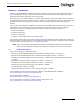
Dialogic® DSI SS7MD Programmer’s Manual Issue 3 Figure 3.
Appendix A Protocol Configuration Using Discrete Messages A.2 Monitoring Configuration Using Individual Messages To configure the board for monitoring it using individual messages, proceed as follows: 1. Build and send an SSD Reset Request to the SSD module. This contains the parameters to initialize the SSD module. 2. Build and send a Board Reset Request for each board in the system. This message contains the address (or identifier) of the board and the name of the codefile.
Dialogic® DSI SS7MD Programmer’s Manual Issue 3 A.3 Q.SAAL Protocol Configuration Using Individual Messages The process to configure the board for Q.SAAL links using individual messages is closely related to section A.1. The full message sequence is shown diagrammatically in Figure 4. Note: The format of all of the messages is described in Chapter 6, "Message Reference". 1. Build and send an SSD Reset Request (SSD_MSG_RESET) to the SSD module.
Appendix A Protocol Configuration Using Discrete Messages route. See the MTP3 Programmer's Manual for the message definition. Wait for the confirmation message and check the status. Proceed now with the User Part configuration procedure. Once this is complete, issue an MTP Link Activation Request (MTP_MSG_ACT_SL) for each link in the system as required to bring the link into service. Further links, link sets and routes may be dynamically added at runtime using the same message sequences. Figure 4. Q.
Dialogic® DSI SS7MD Programmer’s Manual Issue 3 Appendix B: Thermal guidelines for selecting suitable servers for use with a Dialogic® DSI SS7MDL4 Network Interface Board The Dialogic® DSI SS7MDL4 Network Interface Board is a high performance SS7 board capable of delivering over 30,000 MTP2 packets per second. To achieve such levels of performance, state of the art processors operating at high clock frequencies are used.
Appendix B Thermal guidelines for selecting suitable servers for use with a Dialogic® DSI SS7MDL4 Network Interface Board 184
Dialogic® DSI SS7MD Programmer’s Manual Issue 3 Glossary AAL5 ATM Adaptive Layer part 5 AIS Alarm Indication Signal (Blue alarm). ATM Asynchronous Transfer Mode config.txt A text file used for protocol configuration. ctu An example program that demonstrates how a user application can interface with telephony user parts, such as ISUP and TUP. DPC Destination Point Code. Identifies the address (point code) of the SS7 network node to which a Message Signal Unit (MSU) should be directed.
Glossary PRBS Pseudo Random Bit Sequence. A technique used for bit error rate testing on T1/E1/J1 trunks. Q.SAAL Link conforming to Q.2140/Q.2110/GR-2878. RAI Remote Alarm Indication (Yellow alarm). route An MTP3 concept that determines how signaling is distributed over linksets. A route consists of a destination point code and the linkset ID of one or two linksets over which traffic to the destination node should be routed.
Dialogic® DSI SS7MD Programmer’s Manual Issue 3 Index A API_MSG_CNF_IND message 105 API_MSG_RX_INDT message 75 application programs running under Linux 45 ATM monitoring 35 ATM_CONFIG 137 ATM_STREAM 138, 140 SCCP_TRACE 148 SS7_BOARD 119 STREAM_XCON 124 TCAP_CFG_DGRP 155 TCAP_CONFIG 154 TCAP_TRACE 156 TUP_CFG_CCTGRP 145 TUP_CONFIG 144 country-specific approvals link to 14 B binary file ss7.
Index DSI SS7MDL4 boards 13 event indication messages 102 API_MSG_CNF_IND 105 MGT_MSG_NTP_SYNC 108 MGT_MSG_SS7_EVENT 107 MVD_MSG_LIU_STATUS 106 SSD_MSG_STATE_IND 104 example code for building and sending MVD_MSG_SC_LISTEN message 37 execution Linux 45 Solaris 45 F file suffix for DSI SS7MD Board codefile 18 files installed on Linux 19 installed on Solaris 23 G GCT_get_instance( ) function usage 47 GCT_grab( ) function usage 177 GCT_receive( ) function usage 177 GCT_send( ) function usage 177 GCT_set_inst
Dialogic® DSI SS7MD Programmer’s Manual Issue 3 LIU_MSG_R_CONFIG message 63 LIU_MSG_R_CONTROL message 64 LIU_MSG_R_STATE message 109 LIU_MSG_R_STATS message 110 LIU_SC_DRIVE 122 LIUs switching timeslots 36 log utility 162 logging s7_log 27 M MAP configuration commands MAP_CONFIG 157 MAP_TRACE 157 MAP_CONFIG configuration command 157 MAP_TRACE general configuration command 157 MAP_TRACE command 157 message reference 47 message summary table 115 messages API_MSG_CNF_IND 105 API_MSG_RX_IND 74 API_MSG_RX_INDT
Index DSI SS7MDL4 boards 14 relm( ) function usage 177 removing Development Package Linux 21 route configuration command 134 RPM creation instructions 21 installation 21 packages 22 using management tools 22 running programs under Linux 45 runtime operations 34 S s7_log utility 162 s7_mgt protocol configuration utility 32 s7_mgt utility 172 s7_play utility 165 Safety 14 safety compliance DSI SS7MDL4 boards 14 SCBUS_LISTEN 123 SCCP configuration commands 146 SCCP_CONC_SSR 148 SCCP_CONFIG 146 SCCP_GTT 150 S
Dialogic® DSI SS7MD Programmer’s Manual Issue 3 tick 171 tim 170 V verifying device driver loading 20 visual indicators DSI SS7MDL4 boards 13 W warranty information link to 14 191