
Network Card User Manual
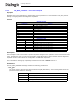
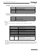
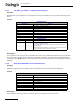
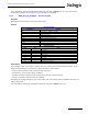
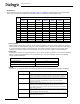
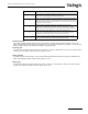
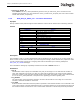
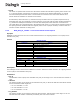
Table Of Contents
- Dialogic® DSI SS7MD Network Interface Board Programmer's Manual
- Contents
- Chapter 1: Introduction
- Chapter 2: Specification
- Chapter 3: Installation
- Chapter 4: Dialogic® DSI SS7MD Board Configuration and Operation
- 4.1 Regulatory and Geographic Considerations
- 4.2 System Structure
- 4.3 Running Host Binaries With Dialogic® DSI SS7MD Board
- 4.4 System Configuration
- 4.5 Protocol Configuration
- 4.6 Monitoring
- 4.7 ATM Monitoring
- 4.8 Switching Timeslots between LIUs
- 4.9 Received Message Timestamping
- 4.10 High Speed Link Operation
- 4.11 Operation of the Thermal Sensor
- Chapter 5: Program Execution
- Chapter 6: Message Reference
- Chapter 7: Configuration Command Reference
- 7.1 Physical Interface Configuration Commands
- 7.2 Monitor Configuration Commands
- 7.3 MTP Configuration Commands
- 7.4 ATM Configuration Commands
- 7.5 ISUP Configuration Commands
- 7.6 TUP Configuration Commands
- 7.7 SCCP Configuration Commands
- 7.8 DTC Configuration Commands
- 7.9 TCAP Configuration Commands
- 7.10 MAP Configuration Commands
- 7.11 INAP Configuration Commands
- 7.12 IS41 Configuration Commands
- Chapter 8: Host Utilities
- Appendix A: Protocol Configuration Using Discrete Messages
- Appendix B: Thermal guidelines for selecting suitable servers for use with a Dialogic® DSI SS7MDL4 Network Interface Board
- Glossary
- Index

65
Dialogic
®
DSI SS7MD Programmer’s Manual Issue 3
The confirmation message (if requested) indicates success with a status value of 0. On receipt of the
confirmation message, the operation to reset the switch is completed.
6.3.6 MVD_MSG_SC_CONNECT – Connect Request
Synopsis
Message sent to the board to control the switch path.
Format
Description
This message is sent to the board to control the cross connect switch. Several different actions can be
performed depending on the value of the mode parameter. These include:
• Cross connect switch to CPU local bus stream connection
• Local bus to cross connect switch connection
• Duplex connection between cross connect switch and CPU local bus stream
• Duplex connection between local bus timeslots
Attempting to use this message in a run mode where the cross connect switch is disabled will result in a
failure return code.
The confirmation message (if requested) indicates success with a status value of 0.
MESSAGE HEADER
Field Name Meaning
type MVD_MSG_SC_CONNECT (0x7e1f)
id 0
src Sending module ID
dst MVD_module_ID
rsp_req Used to request a confirmation.
hclass 0
status 0
err_info 0
len 16
PARAMETER AREA
Offset Size Name
0 2 local_stream
2 2 local_slot
42mode
6 2 source_stream
8 2 source_slot
10 2 dest_stream
12 2 dest_slot
14 2 Reserved. Must be set to 0.