Dialogic ® DSI SS7MD Network Interface Boards Programmer's Manual March 2012 U01SLT www.dialogic.
Copyright and Legal Notice Copyright © 2009-2012 Dialogic Inc. All Rights Reserved. You may not reproduce this document in whole or in part without permission in writing from Dialogic Inc. at the address provided below. All contents of this document are furnished for informational use only and are subject to change without notice and do not represent a commitment on the part of Dialogic Inc. and its affiliates or subsidiaries (“Dialogic”).
Dialogic® DSI SS7MD Network Interface Boards Programmer's Manual Issue 4 Contents Revision History ........................................................................................................... 6 1 Introduction ....................................................................................................... 7 1.1 Related Information ................................................................................................................ 7 2 Specification .....................
Tables 4.4 4.5 4.6 4.7 4.8 4.3.1 LIU_MSG_CONFIG - LIU Configuration Request .............................................................40 4.3.2 LIU_MSG_CONTROL - LIU Control Request ...................................................................44 4.3.3 LIU_MSG_R_CONFIG - LIU Read Configuration Request .................................................46 4.3.4 LIU_MSG_R_CONTROL - LIU Read Control Request .......................................................47 4.3.
Dialogic® DSI SS7MD Network Interface Boards Programmer's Manual Issue 4 Tables Table 1. SS7 Link Capacity of the Dialogic® DSI SS7MDL4 Network Interface Board............................................... 9 Table Table Table Table Table Table Table 2. 3. 4. 5. 6. 7. 8. Dialogic® DSI SS7MD Software Licenses ................................................................................13 Link License Resource Requirements .................................................................................
1 Introduction Revision History Issue Description 4 March 2012 Manual restructured for use in conjunction with Software Environment Programmer’s Manual Issue 9 or later. All config.txt configuration commands moved to that document. 3 July 2009 Description of thermal sensor operation added. 2 May 2009 Support for introduction of ATM termination mode and timestamping. 1 April 2009 Supports the first production release.
Dialogic® DSI SS7MD Network Interface Boards Programmer's Manual Issue 4 1 Introduction Dialogic® DSI SS7MD Network Interface Boards are specialized T1/E1/J1 SS7 signaling boards suitable for use in PCI Express form factor systems. The boards use the common Dialogic® DSI software API to the application that enables applications to be easily ported. The boards provide a hardware platform to enable running Dialogic® DSI Protocol Stacks for the realization of Signaling System Number 7 signaling nodes.
2 Specification 2 Specification This section provides information about: 2.
Dialogic® DSI SS7MD Network Interface Boards Programmer's Manual Issue 4 • Pulse mask — T1: ANSI T1.403 — E1: ITU-T G.703 — J1: TTC JT-G.703 • Data rate — T1: 1544 kbits/s ± 50 ppm — E1: 2048 kbits/s ± 50 ppm — J1: 1544 kbits/s ± 50 ppm • Frame format — T1: F4, D3/D4, ESF, and F72/SLC96 — E1: E1 and E1-CRC4 — J1: J1 frame format • Line codes — T1: B8ZS and AMI — E1: HDB3 and AMI — J1: B8ZS and AMI • Connector type — RJ-48C 2.2.
2 Specification 2.2.4 Protocol Resource Support When terminating SS7 signaling, the DSI SS7MD board runs the SS7 Message Transfer Part, Layer 2 (MTP2) on the board and works in conjunction with higher layer protocols including MTP3, ISUP, SCCP, TCAP, MAP, INAP and IS41 running on the host. The protocols are enabled by software licenses. See Section 2.4, “Software Licenses”. The DSI SS7MDL4 board supports passive monitoring of HDLC format data links including, for example, SS7, LAPB, LAPD, ISDN, and DPNSS.
Dialogic® DSI SS7MD Network Interface Boards Programmer's Manual Issue 4 2.2.8 Physical Specification Form factor Low-profile PCIe Dimensions Board Length 167.65 mm (6.60 inches) Height 68.90 mm (2.731 inches) Packaged Length 277 mm (10.9 inches) Width 180 mm (7.08 inches) Height 55 mm (2.16 inches) Weight 2.2.
2 Specification See http://www.dialogic.com/declarations. • Country-Specific Approvals See the Global Product Approvals list at http://www.dialogic.com/declarations. Alternatively, contact your Dialogic technical sales representative for more information. 2.2.11 Reliability Product reliability is described by: • MTBF Predication 797,000 hours Telcordia SR-232, ground benign @ 40°C • Warranty See Dialogic® Telecom Products Warranty Information at http://www.dialogic.com/warranties. 2.
Dialogic® DSI SS7MD Network Interface Boards Programmer's Manual Issue 4 Table 2. Dialogic® DSI SS7MD Software Licenses Software License Code Link Resources SW LICENSE, 16 LSL SS7SBMDM16 16 SW LICENSE, 32 LSL or 1 MTP or ATM HSL SS7SBMDM32 32 SW LICENSE, 64 LSL, 2 MTP or ATM HSL SS7SBMDM64 64 SW LICENSE, 128 LSL, 4 MTP or ATM HSL SS7SBMDM128 128 SW LICENSE, 256 LSL, 8 MTP or ATM HSL SS7SBMDM256 256 The number of link resources required for each link type is shown below: Table 3.
2 Specification Table 5. Link Type Available by Run Mode Run Mode LSL Links HSL Links LSL Y HSL Y Y ATM Y Y IMA 2.5 ATM Links IMA Links Y Y Y SNMP Support The Dialogic® Distributed Structured Management Information (DSMI) Simple Network Management Protocol (SNMP) Agent provides SNMP monitoring functionality for the Dialogic® DSI SS7 Development Package.
Dialogic® DSI SS7MD Network Interface Boards Programmer's Manual Issue 4 3 SS7MD Board-Specific Configuration and Operation Before attempting software configuration, you should gain an understanding of the flexibility of the protocol stack, the run-time options that exist and the mechanisms that are used to select specific features.
3 SS7MD Board-Specific Configuration and Operation Note: The ss7.dc6 and ss7mcd code files are distributed as part of the Dialogic® DSI Development Package. The ima.dc6 code file is available on request. The code file requires a host license which enables the software to run on the board, details on how to use a Host License are given in the Dialogic® Distributed Signaling Interface Components Host Licensing User Guide. 3.
Dialogic® DSI SS7MD Network Interface Boards Programmer's Manual Issue 4 3.3 ATM Monitoring The system can also be used to monitor AAL5 traffic that is running over ATM links. The following is an example config.txt configuration file to support AAL5 Monitoring: ******************************************************************************** * Example Protocol Configuration File (config.txt) for use with * Dialogic(R) DSI SS7MD Network Interface Boards.
3 SS7MD Board-Specific Configuration and Operation 3.4 Switching Timeslots between LIUs The Dialogic® DSI SS7MD Boards support multiple T1/E1/J1 Line Interface Units (LIUs). The onboard signaling processor handles the SS7 signaling timeslots, while the remaining circuits (voice or data bearer circuits) are switched to another onboard LIU for distribution to other boards. Communication between the application and the board is message-based.
Dialogic® DSI SS7MD Network Interface Boards Programmer's Manual Issue 4 Figure 1. Switch Connections 3.4.2 Static Initialization Static initialization is handled by the s7_mgt protocol configuration utility. For each T1/E1/J1 Line Interface Unit (LIU), the user should include an LIU_SC_DRIVE command in the config.txt protocol configuration file. The LIU_SC_DRIVE command has several parameters. The board_id and liu_id parameters together uniquely identify the affected LIU.
3 SS7MD Board-Specific Configuration and Operation 3.4.3 Dynamic Operation The application controls dynamic changes to switching by sending the MVD_MSG_SC_LISTEN message to the board. This message contains the liu_id (in the range 0 to one less than the number of LIUs), the timeslot number on the T1/E1/J1 interface and the switch channel number (sc_channel) to which the timeslot should listen.
Dialogic® DSI SS7MD Network Interface Boards Programmer's Manual Issue 4 pptr = get_param(m); memset(pptr, 0, m->len); /* * Enter the parameters in machine independent format: */ rpackbytes(pptr, MVDMO_SCLIS_liu_id, (u32)liu_id, MVDMS_SCLIS_liu_id); rpackbytes(pptr, MVDMO_SCLIS_timeslot, (u32)timeslot, MVDMS_SCLIS_timeslot); rpackbytes(pptr, MVDMO_SCLIS_sc_channel, (u32)sc_channel, MVDMS_SCLIS_sc_channel); m->hdr.dst = MVD_TASK_ID; m->hdr.
3 SS7MD Board-Specific Configuration and Operation Figure 2. Drop and Insert 3.5 High Speed Link Operation High Speed Link (HSL) operation is supported in the following mode: • Structured mode, where the data stream is framed as for conventional SS7: — For T1, 8 bits in each of 24 timeslots are available for signaling. — For E1, timeslot 0 is used for framing and 31 timeslots are available for signaling.
Dialogic® DSI SS7MD Network Interface Boards Programmer's Manual Issue 4 The temperature of the boards within a system are periodically measured, and should the temperature of any board exceed a fixed safety threshold then a warning will be provided to the host chassis that the threshold has been passed, a MGT_MSG_EVENT_IND message with a status field of 0xc0 (Exceeded Thermal Threshold) will be sent to SIU_MGT_TASK_ID (0xdf).
4 Message Reference 4 4.1 Message Reference Overview This section describes the individual messages that may be sent to or received from a Dialogic® DSI SS7MD Board. Some messages are sent by the user's application software, while others are sent by utility programs such as the s7_mgt protocol configuration utility. Prior to sending any message to the board, the application should call the GCT_set_instance( ) library function to select which board the message will be sent to.
Dialogic® DSI SS7MD Network Interface Boards Programmer's Manual Issue 4 Message Type Mnemonic Description 0x1213 Confirmation of SS7_MSG_TRACE_MASK 0x126d Confirmation of ATM_MSG_TRACE_MASK 0x1e36 Confirmation of LIU_MSG_R_STATS 0x1e37 Confirmation of LIU_MSG_R_CONFIG 0x1e38 Confirmation of LIU_MSG_R_CONTROL 0x1e39 Confirmation of LIU_MSG_R_STATE 0x2214 Confirmation of SS7_MSG_R_STATS 0x2215 Confirmation of SS7_MSG_R_STATE 0x2263 Confirmation of ATM_MSG_R_STREAM_STATS 0x2266 Confirma
4 Message Reference Message Type 26 Mnemonic Description 0x3f17 Confirmation of MGT_MSG_L1_CONFIG 0x3f18 Confirmation of MGT_MSG_L1_END 0x5213 SS7_MSG_TRACE_MASK Set Trace Mask Request 0x526d ATM_MSG_TRACE_MASK Set ATM Trace Mask Request 0x5e36 LIU_MSG_R_STATS LIU Read Statistics Request 0x5e37 LIU_MSG_R_CONFIG LIU Read Configuration Request 0x5e38 LIU_MSG_R_CONTROL LIU Read Control Request 0x5e39 LIU_MSG_R_STATE LIU Read State Request 0x6136 DVR_MSG_R_L1_STATS Link Statistics R
Dialogic® DSI SS7MD Network Interface Boards Programmer's Manual Issue 4 Message Type 4.1.
4 Message Reference 4.1.3 Message Status Summary The following table shows the valid responses when a response request (rsp_req) is requested in a message. Table 8.
Dialogic® DSI SS7MD Network Interface Boards Programmer's Manual Issue 4 4.2 General Configuration Messages General configuration messages are typically issued by the s7_mgt protocol configuration utility, in which case they need not, and should not, be generated by any user application software.
4 Message Reference The confirmation message (if requested) indicates success with a status value of 0. Parameters The SSD_MSG_RESET message includes the following parameters: mgmt_id The module ID of the management module to which SSD should send board status indications. num_boards The maximum number of boards that ssd is required to manage. This should not exceed eight. 4.2.2 SSD_MSG_RST_BOARD - Board Reset Request Synopsis Reset a single board and download a code file.
Dialogic® DSI SS7MD Network Interface Boards Programmer's Manual Issue 4 The confirmation message (if requested) indicates success with a status value of 0. This implies that the reset operation has commenced, but does not imply completion. The application should then wait until a Board Status Indication message is received that indicates either successful completion of the reset and download operation or failure during the procedure.
4 Message Reference code_file_ext This parameter contains a string definition of a code file path and name, including a null terminating character. If the code_file parameter is set to a null value, the code_file_ext parameter will be used. If the code_file parameter is set to a value other than null, this will take precedence and the data in the code_file_ext parameter will be discarded. 4.2.
Dialogic® DSI SS7MD Network Interface Boards Programmer's Manual Issue 4 Parameters The SSD_MSG_BOARD_INFO message includes the following parameters: board_id The board_id should be set to the logical board number or alternatively, if geographic addressing is enabled, to the board’s physical address. ssdmode Returns the geographic address mode in which the ssdm module is running. This was specified at system start-up in the system.
4 Message Reference 4.2.4 MGT_MSG_CONFIG0 - Board Configuration Request Synopsis Message sent to a board immediately after starting the code running to provide physical configuration parameters. Note: When using the s7_mgt protocol configuration utility, this message is generated by s7_mgt and should not be generated by the user.
Dialogic® DSI SS7MD Network Interface Boards Programmer's Manual Issue 4 config_type Set to 3 when using a DSI SS7MD Board. A separate link layer configuration message should be sent for each link using the MGT_MSG_L1_CONFIG message. flags Global flags with the following bit significance: — Bit 15 is set to 1 for diagnostics purposes to cause the results of board configuration to be passed to the host.
4 Message Reference 4.2.5 MGT_MSG_L1_CONFIG - Layer 1 Configuration Request Synopsis Message sent to a board after successful processing of the MGT_MSG_CONFIG0 message to configure the layer 1 links. Note: When using the s7_mgt protocol configuration utility, this message is generated by s7_mgt and should not be generated by the user.
Dialogic® DSI SS7MD Network Interface Boards Programmer's Manual Issue 4 l1_resource_id The logical identity of the link set, in the range 0 to one less than the number of link sets supported, The linkset_id is used in other commands for reference data_rate Used for setting the link operation. The following table shows the permitted values and their meaning. Value Data Rate 0 64 kbits/s 1 56 kbits/s 2 48 kbits/s link_source Configure the signaling source. Set to 0 for DSI SS7MD Board.
4 Message Reference timeslot_mask Signaling timeslot mask. This field is used to configure HSL links. Bits 0 to 31 of the mask correspond to timeslots 0 to 31 of the signaling stream identified by the link_stream parameter. The recommended bits masks values are: Value 4.2.
Dialogic® DSI SS7MD Network Interface Boards Programmer's Manual Issue 4 4.3 Hardware Control Messages Hardware control messages are used to control various hardware devices on the board, including the T1/E1/J1 Line Interface Units (LIUs), the digital cross connect switches and the clocking mode for the board. In a static configuration, these hardware blocks can be set up using the s7_mgt protocol configuration utility along with the appropriate commands in the config.txt protocol configuration file.
4 Message Reference 4.3.1 LIU_MSG_CONFIG - LIU Configuration Request Synopsis Message sent by the application to establish the operating mode for a Line Interface Unit (LIU). Note: When using the s7_mgt protocol configuration utility, this message is generated by s7_mgt as a result of the LIU_CONFIG command. It therefore need not be generated by the user.
Dialogic® DSI SS7MD Network Interface Boards Programmer's Manual Issue 4 Parameters A description of the permitted parameter values are given below. When the board is initially configured, the LIUs are initialized to a disabled condition. The message includes the following parameters: liu_type The physical interface type according to the following table. The preferred method for configuring an E1 interface is to set a value of 5. Value Description 1 Disabled (used to deactivate a LIU).
4 Message Reference crc_mode The CRC mode. The following table shows the permitted values and their meanings. Value Description 1 CRC generation disabled 2 CRC4 enabled (frame_format must be set to 2) 4 CRC6 enabled (frame_format must be set to 7) build_out The following table shows the permitted values and their meanings.
Dialogic® DSI SS7MD Network Interface Boards Programmer's Manual Issue 4 ais_gen The (initial) mode used to generate the Alarm Indication Signal (Blue alarm). The user may subsequently modify the setting of the outgoing signal using the LIU_MSG_CONTROL message. The following table shows the permitted values and their meanings.
4 Message Reference 4.3.2 LIU_MSG_CONTROL - LIU Control Request Synopsis Message sent by the application to dynamically control operation for a Line Interface Unit (LIU). Allows setting of outgoing alarms and diagnostic loopbacks. Format MESSAGE HEADER Field Name Meaning type id src dst rsp_req hclass status err_info len LIU_MSG_CONTROL (0x7e35) liu_id (in the range 0 to one less than the number of LIUs) Sending module ID MVD_module_ID Used to request a confirmation.
Dialogic® DSI SS7MD Network Interface Boards Programmer's Manual Issue 4 Value Description 0 Do not change AIS/Blue alarm generation mode 1 Disabled; do not generate AIS/Blue alarm 2 Enabled; generate AIS/Blue alarm loop_mode The diagnostic loopback mode. The following table shows the permitted values and their meanings.
4 Message Reference 4.3.3 LIU_MSG_R_CONFIG - LIU Read Configuration Request Synopsis Message sent by the application to read back the current Line Interface Unit (LIU) configuration from the board. Format MESSAGE HEADER Field Name Meaning type id src dst rsp_req hclass status err_info len LIU_MSG_R_CONFIG (0x5e37) liu_id (in the range 0 to one less than the number of LIUs) Sending module ID MVD_module_ID Used to request a confirmation.
Dialogic® DSI SS7MD Network Interface Boards Programmer's Manual Issue 4 4.3.4 LIU_MSG_R_CONTROL - LIU Read Control Request Synopsis Message sent by the application to read back the current Line Interface Unit (LIU) control options from the board. Format MESSAGE HEADER Field Name Meaning type id src dst rsp_req hclass status err_info len LIU_MSG_R_CONTROL (0x5e38) liu_id (in the range 0 to one less than the number of LIUs) Sending module ID MVD_module_ID Used to request a confirmation.
4 Message Reference 4.3.5 MVD_MSG_SC_DRIVE_LIU - LIU Switch Initialization Synopsis Sets up a static switch path through the board between a CPU local bus timeslot and a switching channel.
Dialogic® DSI SS7MD Network Interface Boards Programmer's Manual Issue 4 ts_mask A 32-bit timeslot mask where each bit position represents a local stream timeslot to be connected to the cross connect switch. The least significant bit (bit 0) represents timeslot 0. The arrangement of CPU local bus stream timeslot connections to cross connect switch channels is controlled by the mode parameter. mode The mode of operation that controls how the switch channels are allocated.
4 Message Reference Parameters liu_id The identifier of the T1/E1/J1 LIU in the range of 0 to one less than the number of LIUs. timeslot The timeslot number of the T1/E1/J1 LIU on which the data from the switch channel will be transmitted. Valid ranges for T1/J1 are 1 to 24 and for E1 are 1 to 31. sc_channel The channel number on the switch to which the LIU will listen. This should be in the range of 0 to one less than the total number of channels provided by the cross connect switch. 4.3.
Dialogic® DSI SS7MD Network Interface Boards Programmer's Manual Issue 4 4.3.8 MVD_MSG_SC_CONNECT - Connect Request Synopsis Message sent to the board to control the switch path. Format MESSAGE HEADER Field Name Meaning type id src dst rsp_req hclass status err_info len MVD_MSG_SC_CONNECT (0x7e1f) 0 Sending module ID MVD_module_ID Used to request a confirmation.
4 Message Reference Mode Required Parameters local_ stream local_slot source_ stream source_ timeslot dest_ stream dest_ timeslot pattern 1 *1 *1 * * 0 0 0 2 * * 0 0 * * 0 3 *1 *1 * * * * 0 4 *1 *1 0 0 0 0 0 5 * * 0 0 0 0 0 6 *1 *1 0 0 0 0 0 8 *1 *1 * * 0 0 0 11 *1 *1 * * 0 0 0 12 *1 *1 *1 *1 0 0 0 13 *1 *1 *1 *1 0 0 0 * indicates that the parameter is required, 1 indicates that CPU local bus stream values are invalid.
Dialogic® DSI SS7MD Network Interface Boards Programmer's Manual Issue 4 Value Meaning 1 Make a simplex connection from a timeslot on the cross connect switch to a timeslot on the local bus. Use the local_stream, local_slot, source_stream, and source_slot parameters to specify the local and switch timeslots, respectively. 2 Make a simplex connection from a timeslot on the CPU local bus stream to a timeslot on the cross connect switch.
4 Message Reference dest_stream The dest_stream references the cross connect switch streams that should be used as a destination for data. The parameter takes values in the range of 0 to 31. dest_slot The dest slot references the timeslot from which to connect or disconnect to the cross connect switch stream. The dest slot values are in the range of 0 to 127. 4.3.9 MVD_MSG_SC_MULTI_CONNECT - Multiple Connect Request Synopsis Message sent to the board to control the switch to connect multiple paths.
Dialogic® DSI SS7MD Network Interface Boards Programmer's Manual Issue 4 timeslot_mask A 32-bit mask representing up to 32 timeslots on the local stream. Bit 0 corresponds to timeslot 0. A 1 in the mask indicates that the pattern should be output on this timeslot, a 0 indicates that it should be left unchanged. mode The mode of operation. The following table shows the permitted values and their meaning.
4 Message Reference 4.4 Signaling Interface Messages Signaling interface messages allow signaling links to be activated and deactivated by the user and provide a mechanism for communication between the MTP3 module and the user part module (for example, ISUP or SCCP). In many cases, the user part module is an Dialogic® DSI Protocol Stack so the user does not need to handle the MTP primitives as they pass directly between MTP3 and the user part module.
Dialogic® DSI SS7MD Network Interface Boards Programmer's Manual Issue 4 4.4.1 API_MSG_RX_IND - Received Data Indication Synopsis Message sent from MTP2 to MTP3 containing valid received Message Signal Units (MSU). This message may be visible to the user when tracing is enabled. The message is also used when monitoring LSL or HSL to convey the received MSU to the user.
4 Message Reference 4.4.2 API_MSG_TX_REQ - MTP2 Transmission Request Synopsis Message issued to the board by MTP3, containing an SS7 Message Signal Unit (MSU) for transmission on the specified link. Format MESSAGE HEADER Field Name Meaning type id src dst rsp_req hclass status err_info len API_MSG_TX_REQ (0xcf00) l2_llid Sending module ID MTP2 module ID Sending layers bit set if response is required. 0 0 0 Number of octets in the Signaling Unit.
Dialogic® DSI SS7MD Network Interface Boards Programmer's Manual Issue 4 4.5 ATM Interface Messages ATM Interface Messages allow management of ATM Cell Streams and configuration of Monitoring for AAL5 links.
4 Message Reference Description This message is sent to each board that needs to run ATM protocols to initialize all per module options. It must be the first message sent to the module. Parameters The ATM_MSG_CONFIG message includes the following parameters: options Bit Description 0 Use ATM Forum Idle cell format rather than ITU.
Dialogic® DSI SS7MD Network Interface Boards Programmer's Manual Issue 4 4.5.2 ATM_MSG_CFG_STREAM - ATM Cell Stream Configuration Synopsis Message used to configure an ATM cell stream. Format MESSAGE HEADER Field Name Meaning type id src dst rsp_req hclass status err_info len ATM_MSG_CFG_STREAM (0x7261) Cell Stream ID Management module ID ATM_module_ID Used to request a confirmation.
4 Message Reference options Bit Note: Mnemonic Description 0 ATM_CFG_OPTIONS_SCRAMBLE Enable payload scrambling 1 ATM_CFG_OPTIONS_COSET Use ATM coset in HEC calculation 2 ATM_CFG_OPTIONS_AUTOCORRECT Autocorrect invalid cells if possible 3 ATM_CFG_OPTIONS_IMA_BUNDLE Configuration describes an IMA bundle Either Payload Scrambling or ATM Coset mode, or both, must be enabled for correct operation. Configurations which disable both options will be rejected.
Dialogic® DSI SS7MD Network Interface Boards Programmer's Manual Issue 4 Note: The default vpi/vci combination configured here must not be specified for any AAL5 link on this cell stream. tdm_stream TDM streams to be used by the cell stream. If IMA is active, the parameter is a bitmap of the TDMs to be used by the bundle (bit 0 = TDM 0, etc.). If IMA is not active, the parameter identifies the TDM to be used. tdm_timeslot Bitmap of active timeslots within the above TDM streams.
4 Message Reference 4.5.4 API_MSG_RX_IND - Received AAL5 Monitoring Data Indication Synopsis Message generated by ATM module when operating in AAL5 monitoring mode to convey received frames to the user. Format MESSAGE HEADER Field Name Meaning API_MSG_RX_IND (0x8f01) type id src dst rsp_req hclass status err_info next len upper_id ATM module ID user module ID 0 0 0 0 0 Length of SU data plus 2.
Dialogic® DSI SS7MD Network Interface Boards Programmer's Manual Issue 4 4.5.5 API_MSG_RX_ERR - Received AAL5 Monitoring Error Synopsis Message generated by ATM module (when operating in AAL5 monitoring mode and tracing is enabled) on receipt of an errored frame. The Status field indicates the error type.
4 Message Reference Status Error code returned in the status field.
Dialogic® DSI SS7MD Network Interface Boards Programmer's Manual Issue 4 4.5.6 ATM_MSG_R_STREAM_STATS - Per ATM Cell Stream Statistics Synopsis Message used to retrieve and optionally reset per cell stream statistics. Format MESSAGE HEADER Field Name Meaning type id src dst rsp_req hclass status err_info len ATM_MSG_R_STREAM_STATS (0x6263) Cell Stream ID Sending module ID ATM_module_ID Used to request a confirmation.
4 Message Reference rx_frames Number of valid AAL5 frames received. rx_octets Number of data octets received. rx_discards Number of received AAL5 frames discarded. rx_errors Number of frames with errors received. tx_frames Number of valid AAL5 frames sent. tx_octets Number of data octets sent. tx_discards Number of sent AAL5 frames discarded. tx_errors Number of transmit errors.
Dialogic® DSI SS7MD Network Interface Boards Programmer's Manual Issue 4 4.5.7 ATM_MSG_AAL_CFG_MON_LINK - Configure AAL Monitor Link Synopsis Message used to configure AAL5 monitoring for a specific vpi/vci combination on an existing ATM cell stream. Format MESSAGE HEADER Field Name Meaning type id src dst rsp_req hclass status err_info len ATM_MSG_AAL_CFG_MON_LINK (0x7264) link_id Sending module ID ATM_module_ID Used to request a confirmation.
4 Message Reference Parameters The ATM_MSG_AAL_CFG_MON_LINK has the following parameters: options Bit Meaning 0 Monitor an AAL5 stream 1 Enable timestamping. When enabled, received messages are passed to the user using the API_MSG_RX_INDT message. Otherwise the API_MSG_RX_IND message is used. This option is provided for backwards compatibility and is not recommended for new designs. Others Reserved for future use and must be set to 0.
Dialogic® DSI SS7MD Network Interface Boards Programmer's Manual Issue 4 4.5.8 ATM_MSG_AAL_END_LINK - Remove AAL Link Synopsis Message used to terminate and remove the configuration of a monitoring link. Format MESSAGE HEADER Field Name type id src dst rsp_req hclass status err_info len Meaning ATM_MSG_AAL_END_LINK (0x7265) link_id Sending module ID ATM_module_ID Used to request a confirmation.
4 Message Reference 4.5.9 ATM_MSG_R_AAL_LINK_STATS - Per Monitored Link Statistics Synopsis Message used to retrieve (and reset) per monitored link statistics. Format MESSAGE HEADER Field Name Meaning type id src dst rsp_req hclass status err_info len ATM_MSG_R_AAL_LINK_STATS (0x6266) link_id Sending module ID ATM_module_ID Used to request a confirmation.
Dialogic® DSI SS7MD Network Interface Boards Programmer's Manual Issue 4 oversized_SDUs Total number of oversized SDU errors that have occurred. 4.5.10 ATM_MSG_STREAM_STATE - ATM Stream Status Indication Synopsis Primitive generated by ATM to advise management of changes to the stream state.
4 Message Reference 4.5.11 ATM_MSG_LINK_STATE –AAL Link Status Indication Synopsis Primitive generated by AAL to advise management of changes to the link state. Format MESSAGE HEADER Field Name type id src dst rsp_req hclass status err_info len Meaning ATM_MSG_LINK_STATE (0x026b) link_id ATM Module ID Management Module ID 0 0 Stream state (see table below) Timestamp 0 Description Sent by the ATM module when an AAL link becomes active or inactive.
Dialogic® DSI SS7MD Network Interface Boards Programmer's Manual Issue 4 4.5.12 ATM_MSG_TRACE_MASK - Set Trace Mask Request Synopsis Message issued to ATM module to set the mask on which messages should be traced Format MESSAGE HEADER Field Name Meaning type id src dst rsp_req hclass status err_info len ATM_MSG_TRACE_MASK (0x526d) Link ID User Module ID ATM_TASK_ID Used to request a confirmation 0 0 0 6 PARAMETER AREA Offset 0 2 4 Size 2 2 2 Name op_evt_mask ip_evt_mask Reserved. Set to 0.
4 Message Reference op_evt_mask The output event trace mask. This is a 16-bit value with bits set to 1 to cause a trace message to be sent to the management module whenever a message is issued by ATM. Care should be taken when tracing messages because the system throughput may be reduced. The fields in the trace mask cause the events indicated in the table below to be traced..
Dialogic® DSI SS7MD Network Interface Boards Programmer's Manual Issue 4 4.6 Q.SAAL Interface Messages Q.SAAL Interface Messages allow Q.SAAL links to be configured, activated, and deactivated by the user. The list of management requests sent to Q.SAAL includes: QSL_MSG_CFG_LINK - Configure Q.SAAL Link QSL_MSG_CFG_TIMERS - Configure Timers per Q.SAAL Link QSL_MSG_END_LINK - Remove Q.SAAL Link SS7_MSG_TRACE_MASK - Set Trace Mask Request (Q.SAAL) SS7_MSG_R_STATE - Read Link State Request (Q.
4 Message Reference 15 17 19 21 23 25 27 29 31 33 35 37 39 41 43 45 2 2 2 2 2 2 2 2 2 2 2 2 2 2 2 1 cong_onset cong_abate cong_discard MaxCC MaxPD n1 co1 co2 co3 ca1 ca2 ca3 cd1 cd2 cd3 trace_id Description This message is used to configure the operational parameters for an individual Q.SAAL link and to cause the power up action defined in Q.2140/Q.2110 to be executed. One such message must be issued to Q.SAAL for each link to be used. The QSAAL_MSG_TIMERS message can be used to modify timer values.
Dialogic® DSI SS7MD Network Interface Boards Programmer's Manual Issue 4 upper_mod_id The recipient module ID for the link. vpi The vpi of the AAL5 stream to use. The vpi must be viable in the mask configured in the ATM_MSG_CONFIG message. vci The vci of the AAL5 stream to use. The vci value must be viable in the mask specified in the ATM_MSG_CONFIG message. Values 0, 3 and 4 are reserved.
4 Message Reference ca1 <= co1 <= ca2 <= co2 <= ca3 <= co3 and co1 <= cd1 <= co2 <= cd2 <= co3 <= cd3. trace_id ID of trace module for trace messages. If the trace_id field is zero, then all trace messages, for that link, are sent to the management ,module 4.6.2 QSL_MSG_CFG_TIMERS - Configure Timers per Q.SAAL Link Synopsis Configure timers for an individual Q.
Dialogic® DSI SS7MD Network Interface Boards Programmer's Manual Issue 4 Description QSAAL_MSG_CFG_LINK messages may be issued to the Q.SAAL module to modify timer configuration parameters. Otherwise default timer values will be used.
4 Message Reference 4.6.3 QSL_MSG_END_LINK - Remove Q.SAAL Link Synopsis Remove a Q.SAAL Link - only allowed when the link is in the inactive state. Format MESSAGE HEADER Field Name type id src dst rsp_req hclass status err_info len Meaning QSL_MSG_END_LINK (0x7269) Link ID User Module ID QSL_TASK_ID Used to request a confirmation 0 0 0 0 Description Sent by the user to deactivate a link, remove its connection from the underling ATM cell stream and release its resources.
Dialogic® DSI SS7MD Network Interface Boards Programmer's Manual Issue 4 4.6.4 SS7_MSG_TRACE_MASK - Set Trace Mask Request (Q.SAAL) Synopsis Message issued to Q.
4 Message Reference op_evt_mask The output event trace mask. This is a 16-bit value with bits set to 1 to cause a trace message to be sent to the management module whenever a message is issued by Q.SAAL. Care should be taken when tracing messages because the system throughput may be reduced. The fields in the trace mask cause the events indicated in the table below to be traced.
Dialogic® DSI SS7MD Network Interface Boards Programmer's Manual Issue 4 mgmt_evt_mask The management event trace mask. This is a 16-bit value with bits set to 1 to cause an event indication message to be sent to the management module for the events shown. The fields in the trace mask cause the events indicated in Figure 4 on page 110 to be traced. By default, the SL_FAIL, SL_CONG, ERROR and STATE bits are set. Note: Take care when sending trace mask set requests.
4 Message Reference 4.6.5 SS7_MSG_R_STATE - Read Link State Request (Q.SAAL) Synopsis Message sent to Q.SAAL to retrieve current per link state in the same format as MTP2 Format MESSAGE HEADER Field Name Meaning type id src dst rsp_req hclass status err_info len SS7_MSG_R_STATE (0x6215) Link ID User Module ID QSL_TASK_ID Used to request a confirmation 0 0 0 6 PARAMETER AREA Offset 0 1 2 4 Size 1 1 2 2 Name lsc_state cong_status num_msgs num_rtx_msgs Description This message is issued to the Q.
Dialogic® DSI SS7MD Network Interface Boards Programmer's Manual Issue 4 num_rtx_msgs Number of MSU's in retransmit buffer. Unused - always zero. 4.6.6 SS7_MSG_R_STATS - Read Link Statistics Request (Q.SAAL) Synopsis Message sent to Q.SAAL module to retrieve per link statistics in same format as MTP2.
4 Message Reference Description Message used to retrieve Q.SAAL per-link statistics. The statistics are written into the parameter area of the message and the message is returned to the sender. The internal statistics can be reset or left unchanged, depending on the setting of the status field. The message can be used during operation or when link has been stopped. Once the link has been 'ended' the statistics are not available. 4.6.7 MGT_MSG_QSL_EVENT - Q.SAAL Event Indication Synopsis Q.
Dialogic® DSI SS7MD Network Interface Boards Programmer's Manual Issue 4 4.6.8 Value Mnemonic Description 0x11 S7G_CONG_CLR Congestion abatement 0x12 S7G_CONG_DIS Congestion discard 0x20 SCO_RESP Response time out / link failure 0x21 SCO_BGN BGN PDU unacked 0x22 SCO_ER ER PDU unacked 0x23 SCO_BEJ Initialize connection rejected 0x24 SCO_PROT SSCOP Protocol error MGT_MSG_SS7_STATE - Link State Indication (Q.SAAL) Synopsis Indication generated by Q.
4 Message Reference The LINK STATE is coded as shown in the following table: Value 4.6.9 Mnemonic Description 1 IN_SERVICE Entered IN SERVICE state 2 OUT_SERVICE Entered OUT OF SERVICE state 3 INIT_ALIGN Entered INITIAL ALIGNMENT state Primitives issued from MTP3-b The following primitives are supported by the Q.SAAL module. For message definitions refer to Dialogic® SS7 Protocols MTP2 Programmer's Manual.
Dialogic® DSI SS7MD Network Interface Boards Programmer's Manual Issue 4 4.6.10 Primitives issued to MTP3-b The following primitives are supported by the Q.SAAL module. For message definitions refer to Dialogic® SS7 Protocols MTP2 Programmer's Manual.
4 Message Reference 4.7 Event Indication Messages Event indication messages are the mechanism by which protocol and software error events are reported to the application. These messages are generated asynchronously by different modules within the stack.
Dialogic® DSI SS7MD Network Interface Boards Programmer's Manual Issue 4 4.7.2 SSD_MSG_STATE_IND - Board Status Indication Synopsis Message sent to the application on completion of the reset and download sequence or on detection of a board status event. Note: This message is not required when using the s7_mgt protocol configuration utility.
4 Message Reference board_type Set to 16 for SS7MD. failure_code Value 4.7.3 Meaning 0x0000 undefined 0x00d7 Thermal failure API_MSG_CNF_IND - Configuration Completion Status Indication Synopsis Message issued by the s7_mgt protocol configuration utility on completion of initial configuration sequence.
Dialogic® DSI SS7MD Network Interface Boards Programmer's Manual Issue 4 completion_status The result of initial configuration. The following table shows the possible values and their meanings. Value 4.7.4 Meaning 0 Success 1 Error opening the config.txt protocol configuration file 2 Syntax or value error in the config.
4 Message Reference liu_status The LIU status. The following table shows the possible values and their meanings. Value 4.7.5 Mnemonic State 10 LIUS_SYNC_LOSS Frame Sync Loss 11 LIUS_IN_SYNC Frame Sync OK 12 LIUS_AIS AIS Detected 13 LIUS_AIS_CLRD AIS Cleared 14 LIUS_REM_ALARM Remote Alarm 15 LIUS_REM_ALM_CLRD Remote Alarm Cleared 20 LIUS_PCM_LOSS PCM Loss 21 LIUS_PCM_OK PCM Restored MGT_MSG_SS7_EVENT - MTP2 Q.
Dialogic® DSI SS7MD Network Interface Boards Programmer's Manual Issue 4 • a proving failure (prefixed S7P_) The MGT_MSG_SS7_EVENT message header includes the following field: Event Code The type of event. The following table indicates the possible values and their meanings.
4 Message Reference 4.8 Status Request Messages Status request messages can be used to poll the status of modules or systems running on the board. The messages in the status request category include: LIU_MSG_R_STATE - LIU Read State Request LIU_MSG_R_STATS - LIU Read Statistics Request MGT_MSG_R_BRDINFO - Read Board Info Request DVR_MSG_R_L1_STATS – Layer 1 Link Statistics Request 4.8.
Dialogic® DSI SS7MD Network Interface Boards Programmer's Manual Issue 4 Value 4.8.2 Description 0 OK 1 PCM Loss 2 AIS 3 Sync Loss 4 Remote Alarm LIU_MSG_R_STATS - LIU Read Statistics Request Synopsis Message used to read back performance statistics associated with a Line Interface Unit (LIU).
4 Message Reference Description This message is used to collect performance statistics for a given Line Interface Unit (LIU). A module requesting LIU statistics information is required to complete the version parameter of the message, request a response, and set all additional parameter values to zero. The confirmation message contains a non-zero status in the event of an error.
Dialogic® DSI SS7MD Network Interface Boards Programmer's Manual Issue 4 prbs_status The status of Pseudo Random Bit Sequence (PRBS) indications. - 1 = PRBS is valid, the counts are correct. - 3 = PRBS sequence is not synchronized. 4.8.3 MGT_MSG_R_BRDINFO - Read Board Info Request Synopsis Message used to request basic board information.
4 Message Reference board_rev The board revision number. Currently 0. bsn The board’s production serial number (ASCII characters, null terminated) cur_temp Signed 8-bit value containing the current temperature of the board within the range 128 to 127 degrees Celsius. max_temp Signed 8-bit value containing the maximum temperature the board has reached since SSDM was last started. Value is within the range -128 to 127 degrees Celsius. 4.8.
Dialogic® DSI SS7MD Network Interface Boards Programmer's Manual Issue 4 Description This message provides the user with a number of statistics on a per link basis. If the user sends the message status set to 1 the statistics are reset after being read. Parameters The DVR_MSG_R_L1_STATS message includes the following parameters: duration Duration in tenths of a second since the statistic counters were last reset. abort_cnt The number of aborts received on the link.
Appendix A - Protocol Configuration Using Discrete Messages Appendix A - Protocol Configuration Using Discrete Messages This appendix provides guidelines for protocol configuration using individual messages. A.1 Protocol Configuration Using Individual Messages As an alternative to using the s7_mgt protocol configuration utility it is possible to perform protocol configuration by building and sending messages directly to the board.
Dialogic® DSI SS7MD Network Interface Boards Programmer's Manual Issue 4 6. Build and send an MTP2 Link Configuration Request (SS7_MSG_CONFIG) to set up the MTP2 configuration parameters. See the MTP2 Programmer’s Manual for the message definition. Wait for the confirmation message and check the status. 7. Build and send an MTP3 Module Reset Message (MTP_MSG_RESET) to reset the MTP3 module. See the MTP3 Programmer’s Manual for the message definition. Wait for the confirmation message and check the status.
Appendix A - Protocol Configuration Using Discrete Messages Figure 3.
Dialogic® DSI SS7MD Network Interface Boards Programmer's Manual Issue 4 A.2 Monitoring Configuration Using Individual Messages To configure the board for monitoring it using individual messages, proceed as follows: 1. Build and send an SSD Reset Request to the SSD module. This contains the parameters to initialize the SSD module. 2. Build and send a Board Reset Request for each board in the system. This message contains the address (or identifier) of the board and the name of the code file.
Appendix A - Protocol Configuration Using Discrete Messages A.3 Q.SAAL Protocol Configuration Using Individual Messages The process to configure the board for Q.SAAL links using individual messages is closely related to section A.1 on page 104. The full message sequence is shown diagrammatically in Figure 4. Q.SAAL Configuration Message Sequence Diagram. 1. Build and send an SSD Reset Request (SSD_MSG_RESET) to the SSD module. This message contains the parameters required to initialize the SSD module.
Dialogic® DSI SS7MD Network Interface Boards Programmer's Manual Issue 4 sets and links to support, module_ids for user part modules etc.). See the MTP3 Programmer's Manual for the message definition. Wait for the confirmation message and check the status. For each link in the link set, perform the following: 11.
Appendix A - Protocol Configuration Using Discrete Messages Figure 4. Q.SAAL Configuration Message Sequence Diagram USER_MGT SSD On-Board MGT MTP3 Q.
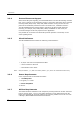
Dialogic® DSI SS7MD Network Interface Boards Programmer's Manual Issue 4 Appendix B - Thermal guidelines for server selection The Dialogic® DSI SS7MDL4 Network Interface Board is a high performance SS7 board capable of delivering over 30,000 MTP2 packets per second. To achieve such levels of performance, state of the art processors operating at high clock frequencies are used.
SS7MDL4 SS7MDL4 Appendix B - Thermal guidelines for server selection CPU CPU FAN FAN Likely to be Adequate SS7MDL4 board is in line with the airflow created by the main fans as they cool the CPUs. In this scenario, the cooling is likely to be adequate to prevent the occurrence of temperature issues. CPU CPU FAN FAN Further tests required SS7MDL4 board is not in line with the airflow created by the main fans.
Dialogic® DSI SS7MD Network Interface Boards Programmer's Manual Issue 4 Glossary of Terms AAL5 ATM Adaptive Layer part 5 AIS Alarm Indication Signal (Blue alarm). ATM Asynchronous Transfer Mode config.txt A text file used for protocol configuration. ctu An example program that demonstrates how a user application can interface with telephony user parts, such as ISUP. DPC Destination Point Code.
Glossary of Terms Q.SAAL Link conforming to Q.2140/Q.2110/GR-2878. RAI Remote Alarm Indication (Yellow alarm). route An MTP3 concept that determines how signaling is distributed over linksets. A route consists of a destination point code and the linkset ID of one or two linksets over which traffic to the destination node should be routed. When two linksets are provided, the user can choose to load share traffic or treat the linksets as primary and secondary.