Dialogic® IMG 1010 Integrated Media Gateway Quick Start Guide April 2009 07-8728-04 www.dialogic.
IMG 1010 Quick Start Guide Copyright and Legal Notice Copyright © 2005-2009 Dialogic Corporation. All Rights Reserved. You may not reproduce this document in whole or in part without permission in writing from Dialogic Corporation at the address provided below. All contents of this document are furnished for informational use only and are subject to change without notice and do not represent a commitment on the part of Dialogic Corporation or its subsidiaries (“Dialogic”).
IMG 1010 Quick Start Guide Hardware Limited Warranty Warranty for Hardware Products: Dialogic Corporation or its subsidiary that originally sold the hardware product to you ("Dialogic") warrants to the original purchaser (“Purchaser”) of this hardware product (“Product”), that at the time of delivery the Product supplied hereunder will be free from defects in material and workmanship. This warranty is for the standard period for such Product set out on Dialogic's website at http://www.dialogic.
IMG 1010 Quick Start Guide Overview This IMG 1010 Quick Start Guide is an abbreviated guide which explains how to connect power and network cabling. For more information on installation and setup, please reference the online documentation at http://www.dialogic.com/manuals. Shipping Information Review the packing list to check that all the items listed on the packing list have been sent. Should any discrepancies exist, contact your Dialogic Representative immediately.
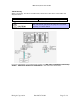
IMG 1010 Quick Start Guide -48vdc wiring When connecting -48 vdc to the IMG 1010, follow the instructions in the table and diagram below. 14 AWG Machine Tool Wire (MTW) DC Power Module Plugs Blue = -48v White = -48v return Dialogic Supplied (In Plastic Bag) The DC power module plugs are polarity-sensitive. The unit will not operate if the plugs are not wired correctly, as shown below.
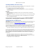
IMG 1010 Quick Start Guide Grounding IMG1010 (DC Version Only) The DC version of the IMG 1010 should be connected to a true earth ground. To connect chassis to ground you will need the following equipment: • 14-16 AWG machine tool wire (MTW) (green/yellow) • # 10 solderless crimp with two-hole mounting option to connect to grounding lug. (Dialogic-supplied). Procedure 1. Remove the two-hole grounding lug at the rear of the IMG 1010 by removing the grounding screws. 2. Crimp the grounding wire to the lug.
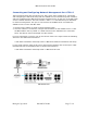
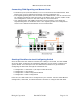
IMG 1010 Quick Start Guide Connecting and Configuring Network Management Port ‘CTRL 0’ The information below will provide the user with a basic setup sequence for connecting and configuring the IMG 1010 along with the GCEMS server to download system software and start configuring the IMG 1010 using the ClientView GUI. On the rear of the IMG 1010 are the network interfaces. The first interface -CTRL 0- is a Fast Ethernet port dedicated to network management.
IMG 1010 Quick Start Guide GCEMS software installation. To take advantage of all new features, it is recommended that the latest version of GCEMS software be installed on the GCEMS Server. The most current software can be obtained from the Dialogic Technical Support website. 1. Go to the Dialogic Support Technical Website at http://www.dialogic.com/support 2. Select ‘Downloads’. You will require a logon username and password to access the downloads site. (A support contract is needed to access this site.
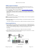
IMG 1010 Quick Start Guide Connecting TDM Signaling and Bearer Ports • The Bearer ports (Interface Offsets) 0-27 are connected to the TDM network. Each Bearer Port can have signaling and bearer channels configured on it. • The Signaling/Timing Ports are connected to the TDM network, and can also be used for signaling and bearer traffic the same as the Bearer ports. See the ‘T1/E1’ under the ‘Configuration’ section in the online help for more information.