
Installation guide

Installing the Dialogic®
Brooktrout® TR1034 Analog
PCI Express Board
Part Number: 931-159-06
The Dialogic® Brooktrout® TR1034 Analog PCI
Express boards (“TR1034” or “TR1034 Board(s)”) are
full-sized, single-slot, PCI Express serial I/O
bus-compatible fax boards. They provide the
following:
On-board analog loop start connections
V.34 (33.6 Kbps) fax transmission speeds
Up to eight fax and voice channels per board
The TR1034 Analog PCI Express Series boards use
3.3V and 12.0V power from the serial bus and can be
inserted into the x4, x8, or x16 bus (signaling) slot.
You need a voice or fax application to use a
TR1034 Analog board. Dialogic does not provide the
application or a driver for this board. Normally, you
purchase the application and driver from a third party
vendor.
This installation guide provides information about:
Safety Compliance Statements
System Requirements (including telephone service)
Setting the Module Number
Installing the TR1034 Board
Recognizing PCI Express Slots
Connecting the Phone Service
Understanding LED Signals
Using the TR1034 Analog Board
Getting Help
Safety Compliance Statements
Install this board only in UL Listed equipment that
has instructions stating that the user may install and
remove accessory boards.
Disconnect any TNV circuit connectors (telephone
line cords) from this board before removing the
cover of the equipment.
System Requirements
This board must be installed in an enclosure that meets
the following specifications:
A Pentium or later host processor
A PCI Express serial I/O bus slot that is at least
x4 wide. See
Recognizing PCI Express Slots for
more information.
Temperature: 0 C - 50 C
Humidity: 10% - 90% (non-condensing)
Power Requirements:
The following is also required:
Telephone service: analog loop start interface
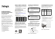
Setting the Module Number
Set each board to a unique module number to easily
identify the resources associated with a specific board
in a multi-board system.
Use the SW-1 rotary switch (Figure 1) to set a unique
module number for each Brooktrout Fax Board. See
Figure 5 for the switch location. Select a number from
2 - F on the rotary switch. Settings 0 and 1 are reserved
and cannot be used.
Figure 1. Rotary Switch (SW-1)
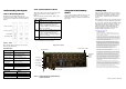
Installing the TR1034 Board
To install your board:
1. Turn off your PC and remove the cover.
2. Locate a free PCI Express bus slot (see Figure 2).
3. Carefully align the board with the slot and firmly
seat the PCI Express Board Edge connector into
the PCI Express slot..
4. Tighten the mounting bracket screw to secure the
board to the chassis.
5. Replace the cover.
6. Turn on your computer.
Note: Brooktrout Fax Boards should not be present in the
computer during the installation of any operating system.
The operating system might misinterpret the board as
being some other device, with unpredictable
consequences.
Recognizing PCI Express Slots
The PCI Express slots in the computer chassis appear
as black slots. The TR1034 Analog board has a PCI
Express board edge connector. It can be inserted into
any one of the PCI Express slots shown in Figure 2.
Figure 2. PCI Express Serial Bus Slots
Connecting the Phone Service
The appropriate telephone service and hookups must
be installed at your site in order to connect to
telephone service. The following table shows the
channel/connector relationship:
Use the cable supplied with the board. Use the
following instructions to connect your board to Analog
Loop Start service:
1. Plug one end of the cable into the RJ-45 telephone
connector on the board.
Connect to Connector A for channels 0-3 or to
Connector B for channels 4-7 (see Figure 4 to
locate connectors).
2. Plug the other end into the wall connector for your
telephone service.
See Figure 3 for pinout details for your board:
Figure 3. Analog Connector Pinouts
Board +3.3V +3.3 Aux +12V Total Power
2 chan
1.4A 0.050A 0.025A 5.1W
4 chan
1.45A 0.050A 0.050A 5.5W
8 chan
1.5A 0.050A 0.10A 6.3W
Caution: A small amount of static electricity can
destroy the sensitive components on your board.
To prevent static damage, always connect yourself
to ground using a ground strap before touching a
circuit board. Handle boards only by the edges or
metal mounting brackets and transport boards in
an anti-static bag.
Warning: When installing the board, be sure that
the mounting bracket is securely fastened to the
chassis and the chassis is plugged into a
grounded three prong plug. Improper chassis or
bracket grounding can result in harmful or fatal
electrical shock as well as component damage.
PCI Express Board
Edge Connector
PCI Express x4 slot
PCI Express x8 slot
PCI Express x16 slot
Insert board connector into any of
these slots
Channel
Number
RJ-45
Connector Type of Service
0
1
2
3
4
5
6
7
A
A
A
A
B
B
B
B
Analog Loop Start
Analog Loop Start
Analog Loop Start
Analog Loop Start
Analog Loop Start
Analog Loop Start
Analog Loop Start
Analog Loop Start
1
2
3
4
5
6
7
8
Pin
Tip 2
Ring 2
Tip 1
Ring 0
Tip 0
Ring 1
Tip 3
Ring 3
Port A
Tip 6
Ring 6
Tip 5
Ring 4
Tip 4
Ring 5
Tip 7
Ring 7
Port B