
User Guide

Installing the Dialogic®
Brooktrout® TR1034 BRI
PCI Express Board
Part Number: 931-162-06
The Dialogic® Brooktrout® TR1034 Basic Rate
Interface ISDN PCI Express board (“TR1034 BRI
board” or “board”) is half-sized, single-slot PCI
Express-bus compatible fax and voice processing
board. It provides the following:
On-board BRI connections
V.34 (33.6 Kbps) fax transmission speeds
Up to four fax and voice channels per board
The TR1034 BRI PCI Express Series board is a single
lane (x4 form factor) cards.
You need a fax or voice application to use a
TR1034 BRI board should you choose to do so.
Dialogic does not provide the application or a driver
for this board. A driver comes with the application
that you purchase.
This installation guide provides information about:
System Requirements (including telephone
service)
Setting the Module Number
Setting Termination Jumpers for the BRI Line
Installing a Dialogic® Brooktrout® TR1034 BRI
Board
Recognizing PCIe Slots
Connecting the Phone Service
Understanding LED Signals
Using a Dialogic® Brooktrout® TR1034 BRI
Board
Getting Help
System Requirements
This board must be installed in an enclosure that
meets the following specifications:
Chassis Requirement: Compliant to the PCI
Express Base Specification, Rev 1.0a
A Pentium or later host processor
A PCIe x4, x8, or x16 bus slot. See Recognizing
PCIe Slots
for more information.
Temperature: 0 C - 50 C
Humidity: 10% - 95% (non-condensing)
Power Requirement (Maximum Load)::
The following is also required:
Telephone service: BRI interface
Options are provided for one or two BRI (2B+D) S/T
interfaces with B and D-channel HDLC support.
Compliant with I.430 ITU S/T ISDN support in
Terminal Equipment (TE) and network terminator
(NT) mode.
Setting the Module Number
Set each board to a unique module number to easily
identify the resources associated with a specific board
in a multi-board system.
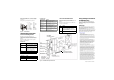
Use the SW-1 rotary switch (Figure 1) to set a unique
module number for each Dialogic® Brooktrout®
board. See Figure 5 for the switch location. Select a
number from 2 - F on the rotary switch. Settings 0 and
1 are reserved and cannot be used.
Figure 1. Rotary Switch (SW-1)
Setting Termination Jumpers
for the BRI Line
Before installing your board, set termination for the
BRI line if necessary. See Figure 5 for the location of
the termination switches.
Set jumpers as follows (See Figure 2 for details):
Figure 2. Termination Jumpers
When the jumpers are removed from both
switches for the appropriate port, there is no
termination.
When jumpers are present, the lines are
terminated with 100 ohms (this is how the board
is shipped).
Dialogic does not support any configuration
except the two illustrated in Figure 2.
Installing a Dialogic
®
Brooktrout
®
TR1034 BRI Board
To install your board:
1. Turn off your PC and remove the cover.
2. If the system has a PCIe expansion hold-down
bar, remove it.
3. Locate a free PCI Express bus slot that is x4 or
larger.
4. Align the board with the slot and firmly seat the
board into the slot. Carefully insert the PCI
Express Board Edge Connector into the PCI
Express Slot to avoid damage to the board.
5. Tighten the mounting bracket screw to secure the
board to the chassis.
6. Replace the cover.
7. Turn on your computer.
Note: Dialogic® Brooktrout® boards should not be present in the
computer during the installation of any operating system.
The operating system might misinterpret the board as being
some other device, with unpredictable consequences.
Recognizing PCIe Slots
The PCIe connectors in the computer chassis usually
appear as white slots. The TR1034 BRI board has a
PCI board edge connector. It can be inserted into any
of the PCIe slots shown in Figure 3.
Figure 3. PCIe Slots
Connecting the Phone Service
You must install the appropriate telephone service and
hookups at your site to connect to telephone service.
The following table shows the channel/port
relationship:
1. Use the cable supplied with the board. To ensure
conformity, shielded cables must be used.
Do the following to connect your board to BRI
service:
1. Plug one end of the cable into the telephone
connector on the board.
Connect to Port A for channels 0 and 1 or to
Port B for channels 2 and 3 (see Figure 5 to
locate ports).
2. Plug the other end into the wall connector for
your BRI service.
Note: Port B is not present on the TR1034 BRI single port version.
Board + 3.3 V + 12 V Total Power
Single Channel 1.1 A 0.A 3.63 W
Dual Channel 1.2 A 0.A 3.96 W
Caution: A small amount of static electricity can
destroy the sensitive components on your board.
To prevent static damage, always connect yourself
to ground using a ground strap before touching a
circuit board. Handle the boards only by the edges
or metal mounting brackets and transport boards
in an anti-static bag.
Warning: When installing the board, be sure that
the mounting bracket is securely fastened to the
chassis and the chassis is plugged into a
grounded three prong plug. Improper chassis or
bracket grounding can result in harmful or fatal
electrical shock as well as component damage.
Jumper is in place
(ISDN BRI line is terminated)
Jumper is removed
(ISDN BRI line is not terminated
)
Channel
Number
RJ-45 Port
Type of
Service
0
1
2
3
A
A
B
B
BRI S/T
BRI S/T
BRI S/T
BRI S/T