
User Guide

Dialogic Corporation © 2004–2008
Before using your BRI service, you must configure
certain parameters. See your software documentation
for details.
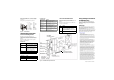
See Figure 4 for pinout details for your board:
Figure 4. Connector Pinouts
Understanding LED Signals
LEDs on the Mounting Bracket
The LEDs on the mounting bracket provide
information about the status of the different systems
on the board. To identify and locate these LEDs, see
Figure 5.
The following tables describe how the end panel
LEDs provide information:
BRI Status LED
Channel LEDs
Board Status LED
Figure 5. TR1034 BRI PCI Express Series Board
LEDs on the TR1034 BRI Board
The LEDs on the board provide information about the
status of the board. To locate these LEDs, see
Figure 5.
The following table describes how the LEDs on the
board provide information:
Using a Dialogic
®
Brooktrout
®
TR1034 BRI Board
Once you have installed the TR1034 BRI board,
install and configure your voice or fax software
application according to instructions included with
the software.
Getting Help
Dialogic provides technical support for customers who have purchased
hardware or software products from Dialogic. If you purchased products
from a reseller, please contact that reseller for technical support.
This equipment contains no user serviceable parts and is not intended for
repair by unauthorized personnel.
If you experience problems with the TR1034 BRI board, please use the web
site below for repair or warranty information. If the equipment is causing
harm to the telephone network, the telephone company might request that
you disconnect the equipment until the problem is resolved.
www.dialogic.com/support/
Copyright and Legal Notice
Copyright © 2004-2008 Dialogic Corporation. All Rights Reserved. You may not
reproduce this document in whole or in part without permission in writing from Dialogic
Corporation at the address provided below.
All contents of this document are subject to change without notice and do not represent a
commitment on the part of Dialogic Corporation or its subsidiaries. Reasonable effort is
made to ensure the accuracy of the information contained in the document. However, due
to ongoing product improvements and revisions, Dialogic Corporation and its subsidiaries
do not warrant the accuracy of this information and cannot accept responsibility for errors
or omissions that may be contained in this document.
INFORMATION IN THIS DOCUMENT IS PROVIDED IN CONNECTION WITH
DIALOGIC® PRODUCTS. NO LICENSE, EXPRESS OR IMPLIED, BY ESTOPPEL OR
OTHERWISE, TO ANY INTELLECTUAL PROPERTY RIGHTS IS GRANTED BY THIS
DOCUMENT. EXCEPT AS EXPLICITLY SET FORTH BELOW OR AS PROVIDED IN A
SIGNED AGREEMENT BETWEEN YOU AND DIALOGIC, DIALOGIC ASSUMES NO
LIABILITY WHATSOEVER, AND DIALOGIC DISCLAIMS ANY EXPRESS OR IMPLIED
WARRANTY, RELATING TO SALE AND/OR USE OF DIALOGIC PRODUCTS
INCLUDING LIABILITY OR WARRANTIES RELATING TO FITNESS FOR A
PARTICULAR PURPOSE, MERCHANTABILITY, OR INFRINGEMENT OF ANY
INTELLECTUAL PROPERTY RIGHT OF A THIRD PARTY.
Dialogic products are not intended for use in medical, life saving, life sustaining, critical
control or safety systems, or in nuclear facility applications.
It is possible that the use or implementation of any one of the concepts, applications, or
ideas described in this document, in marketing collateral produced by or on web pages
maintained by Dialogic Corporation or its subsidiaries may infringe one or more patents or
other intellectual property rights owned by third parties. Dialogic Corporation or its
subsidiaries do not provide any intellectual property licenses with the sale of Dialogic
products other than a license to use such product in accordance with intellectual property
owned or validly licensed by Dialogic Corporation or its subsidiaries. More detailed
information about such intellectual property is available from Dialogic Corporation's legal
department at 9800 Cavendish Blvd., 5th Floor, Montreal, Quebec, Canada H4M 2V9.
The software referred to in this document is provided under a Software License
Agreement. Refer to the Software License Agreement for complete details governing the
use of the software.
Dialogic Corporation encourages all users of its products to procure all necessary
intellectual property licenses required to implement any concepts or applications and does
not condone or encourage any intellectual property infringement and disclaims any
responsibility related thereto. These intellectual property licenses may differ from country
to country and it is the responsibility of those who develop the concepts or applications to
be aware of and comply with different national license requirements. Dialogic, Dialogic
Pro, Brooktrout, Cantata, SnowShore, Eicon, Eicon Networks, Eiconcard, Diva,
SIPcontrol, Diva ISDN, TruFax, Realblocs, Realcomm 100, NetAccess, Instant ISDN,
TRXStream, Exnet, Exnet Connect, EXS, ExchangePlus VSE, Switchkit, N20, Powering
The Service-Ready Network, Vantage, Connecting People to Information, Connecting to
Growth and Shiva, among others as well as related logos, are either registered
trademarks or trademarks of Dialogic. Dialogic's trademarks may be used publicly only
with permission from Dialogic. Such permission may only be granted by Dialogic’s legal
department at 9800 Cavendish Blvd., 5th Floor, Montreal, Quebec, Canada H4M 2V9.
Any authorized use of Dialogic's trademarks will be subject to full respect of the trademark
guidelines published by Dialogic from time to time and any use of Dialogic’s trademarks
requires proper acknowledgement. The names of actual companies and products
mentioned herein are the trademarks of their respective owners.
BRI LED Meaning
Red Layer 1 is down. This can occur if the
cable is wired incorrectly or the CPE
or CO emulation is wrong.
Yellow Layer 1 is up, but layer 2 is down.
This state can occur if the protocol
has not been initialized, the D
channel has not been enabled, or the
clocks have not synchronized.
Green Layer 1 is up, and layer 2 is up.
Red/green The board is currently receiving CRC
errors.
Channel LEDs Meaning
Off Channel is idle.
Flashing green Channel is being set up or is
connected.
1
2
3
4
5
6
7
8
Pin
No connection
No connection
TX Tip 0
RX Tip 0
RX Ring 0
TX Ring 0
No connection
No connection
Port A
No connection
No connection
TX Tip 1
RX Tip 1
RX Ring 1
TX Ring 1
No connection
No connection
Port B
Board Status LED Meaning
Flashing yellow Board is powered up and is
passing self test checks.
Steady red Board is powered up, and the self
test has failed.
Flashing yellow
and green
Board is powered up and is
downloading firmware.
Flashing green Firmware is downloaded, and the
board is in service.
Solid green or
Flickering red
Invalid states. Please reinstall your
board and call Tech Support, if the
condition persists.
Off Board is not powered up.
LED Meaning
DSP Displays the status for the DSP. After the
firmware is loaded and during normal
execution, this LED blinks about every
second. If the LED is not blinking, the DSP
firmware is not running.
Power Steady green indicates good board power.