Dialogic® TX 4000 PCI SS7 Network Interface Board Installation Manual July 2009 64-0429-01 www.dialogic.
Copyright and legal notices Copyright © 2003-2009 Dialogic Corporation. All Rights Reserved. You may not reproduce this document in whole or in part without permission in writing from Dialogic Corporation at the address provided below. All contents of this document are furnished for informational use only and are subject to change without notice and do not represent a commitment on the part of Dialogic Corporation or its subsidiaries (“Dialogic”).
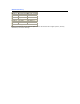
Revision history Revision Release date 62334-10 November 2003 SRR, SS7 4.0 Beta Notes 62334-11 April 2004 SRR, SS7 4.0 62334-12 August 2004 SRR. SS7 4.1 62334-13 April 2005 LBG, SS7 4.2 62334-14 July 2008 LBG, SS7 5.0 64-0429-01 July 2009 LBG, SS7 5.1 Last modified: July 7, 2009 Refer to www.dialogic.com for product updates and for information about support policies, warranty information, and service offerings.
Table Of Contents Chapter 1: Introduction ..........................................Error! Bookmark not defined. Chapter 2: Dialogic® TX 4000 PCI SS7 Network Interface Board Installation Manual...................................................Error! Bookmark not defined. Chapter 3: Overview of the TX 4000 board ....................................................9 TX 4000 board features................................................................................ 9 Software components ...................
Introduction TX 4000 PCI SS7 Network Interface Board Installation Manual Chapter 8: Hardware specifications .............................................................43 General hardware specifications ...................................................................43 Physical .................................................................................................43 Host interface .........................................................................................43 H.
1 Introduction The Dialogic® TX 4000 PCI SS7 Network Interface Board Installation Manual explains how to perform the following tasks: • Install the TX 4000 PCI SS7 Network Interface board • Configure the TX 4000 PCI SS7 Network Interface board • Establish network connections • Verify the installation This manual targets developers of telephony and voice applications who use TX 4000 boards with Dialogic® NaturalAccess™ Signaling Software.
2 Overview of the TX 4000 board TX 4000 board features The Dialogic® TX 4000 PCI SS7 Network Interface board is a PCI board that provides four T1 or E1 digital trunk interfaces and two Ethernet 10/100Base-T interfaces. The TX 4000 design is based on an intelligent communication processor (CP) that plugs into a single PCI bus slot. The CP operates with the PCI bus host processor to form a distributed communications application platform.
Overview of the TX 4000 board TX 4000 PCI SS7 Network Interface Board Installation Manual The following illustration shows the TX 4000 board: Ethernet T1/E1 trunk connectors connectors Ethernet MAC/PHY chips T1/E1 status LEDs S3 DIP switch Framer Host bridge PCI to 60x bridge 8260 Power QUICC II controller T8100A H.100 interface PCI to MPX bridge 7457 RISC microprocessor with fan H.
TX 4000 PCI SS7 Network Interface Board Installation Manual • Overview of the TX 4000 board Telephony bus switching Switching for the TX 4000 board offers support for the H.100 bus within the H.100 architecture. On the TX 4000 board, switch connections are allowed for a total of 256 half duplex or 128 full duplex connections between local devices and the H.100 bus. Switch connections between local devices are non-blocking.
Overview of the TX 4000 board TX 4000 PCI SS7 Network Interface Board Installation Manual Utilities and demonstration programs NaturalAccess Signaling Software provides the following utilities and demonstration programs for the TX 4000 board. Run these programs from the \Program Files\Dialogic\tx\bin directory in Windows and from the /opt/dialogic/tx/bin directory in UNIX. For more information about each utility, refer to the Dialogic® TX Series SS7 Boards TX Utilities Manual.
TX 4000 PCI SS7 Network Interface Board Installation Manual Overview of the TX 4000 board NaturalAccess™ Signaling Software provides the following programs in compiled and uncompiled form to demonstrate the usage of the TDM libraries. For information about these programs, refer to the Dialogic® TX Series SS7 Boards TDM for SS7 Developer's Reference Manual. Program Demonstrates how to... t1demo Test the T1/E1 and H.100 library functions with TX boards in a system.
3 Installing the TX 4000 board System requirements To install and use the TX 4000 board, your system must have the following components: • An available PCI bus slot. • At least 8 MB of memory (excluding operating system requirements). • NaturalAccess software development environment. • NaturalAccess Signaling Software. • A chassis with 3.3 V of supplied power to provide a minimum of 6.5 A per TX 4000 board. • An uninterruptible power supply (UPS).
Installing the TX 4000 board TX 4000 PCI SS7 Network Interface Board Installation Manual Installation summary The following table summarizes the steps for initially installing the hardware and software components: Step Description For details, refer to... 1 Ensure that your system meets the system requirements. System requirements on page 15 2 Power down the system if it is running. 3 Configure the TX 4000 board to control H.100 bus termination if applicable. Configuring H.
TX 4000 PCI SS7 Network Interface Board Installation Manual Installing the TX 4000 board Configuring the hardware This topic describes the following procedures for configuring the TX 4000 board: • Configuring H.100 bus termination • Configuring SS7 Monitor mode • DIP switch S1 Configuring H.100 bus termination The TX 4000 board connects to an H.100 bus. Boards on the H.100 bus are connected to one another with an H.100 bus cable. Enable bus termination on the board located on each end of the H.
Installing the TX 4000 board TX 4000 PCI SS7 Network Interface Board Installation Manual ON 1 2 34 56 7 8 S2 The following illustration shows the H.100 termination DIP switch: OFF Configuring SS7 Monitor mode DIP switch S3 controls the SS7 Monitor mode. The DIP switch is located on the front of the board, to the right of the T1/E1 trunk connectors. By default, all S3 switches are set to the ON position. This setting disables SS7 Monitor mode.
TX 4000 PCI SS7 Network Interface Board Installation Manual Installing the TX 4000 board DIP switch S1 DIP switch S1 controls the operation of the board. By default, only switch 2 (AUTOSTART) is set to the ON position; all other S1 switches are set to the OFF position. Switch 5 is reserved for future use. Do not modify the default settings for this switch. Set switch 8 (SW MIN BOOT) to ON to boot the board to the original software image instead of using the current production software image.
Installing the TX 4000 board TX 4000 PCI SS7 Network Interface Board Installation Manual Installing the board Complete the following steps to install the TX 4000 board in your system: Step Action 1 If necessary, configure the board as described in Configuring the hardware on page 17. 2 Power down the computer and disconnect the power cord from the power source. 3 Remove the cover from the computer and set it aside.
4 Configuring the TX 4000 board Using the configuration utility After you install the TX 4000 board and the NaturalAccess Signaling Software, you must assign a CP number to each TX 4000 board. Verify that you have completed the steps described in the installation summary on page 16 before you proceed to assigning a CP number on page 22. To assign a CP number, you will use the txcpcfg utility.
Configuring the TX 4000 board TX 4000 PCI SS7 Network Interface Board Installation Manual Assigning a CP number Complete the following steps to assign a CP number to an installed TX board: Step Action 1 Power up the system if it is not running. In a Windows system, the Windows® New Hardware Wizard appears and prompts you for the files required to activate the SS7 drivers. Refer to Installing Dialogic® NaturalAccess™ Signaling Software for detailed information.
TX 4000 PCI SS7 Network Interface Board Installation Manual Configuring the TX 4000 board Adding a board Complete the following steps to add a new undefined TX 4000 board: Step Action 1 Power down the system if it is running. 2 Insert the TX 4000 board, seating it firmly in an available slot. 3 Power up the system. If you are installing a TX 4000 board in a Windows system for the first time, the Windows® New Hardware Wizard appears and prompts you for the files required to activate the SS7 drivers.
Configuring the TX 4000 board TX 4000 PCI SS7 Network Interface Board Installation Manual Changing a CP number Complete the following steps to change the CP number of a TX board: Step Action 1 At the prompt, invoke txcpcfg by entering the following command: txcpcfg txcpcfg displays the bus number, slot number, CP number, and CP model of all the TX boards that are present and configured. Bus 2 2 2 Slot 2 4 6 CP Number 1 2 3 CP TX TX TX Model 4000 4000 xxxx where xxxx is 4000 for a TX 4000 board.
TX 4000 PCI SS7 Network Interface Board Installation Manual Configuring the TX 4000 board Moving a board Complete the following steps to move a TX board from one slot to another slot: Step Action 1 Power down the system if it is running. 2 Move the TX 4000 board from one slot to another slot, seating it firmly in the new slot. 3 Power up the system.
Configuring the TX 4000 board TX 4000 PCI SS7 Network Interface Board Installation Manual Removing a board Complete the following steps to remove a TX board from the system: Step Action 1 Power down the system if it is running. 2 Remove the TX 4000 board from the slot. 3 Power up the system.
TX 4000 PCI SS7 Network Interface Board Installation Manual Configuring the TX 4000 board Saving configuration changes In a Windows system, any changes that you make to the configuration information with the txcpcfg utility are saved automatically. In a UNIX system, changes that you make to the configuration information with the txcpcfg utility are deleted when you restart the system.
5 Establishing network connections Connectors and cables The TX 4000 board has two Dialogic® MD1 RJ-45 T1/E1 trunk interfaces and two Ethernet connectors. The following illustration shows these connectors on the TX 4000 end bracket: Trunk 1 (and Trunk 3 if applicable) Trunk 2 (and Trunk 4 if applicable) Ethernet 1 Ethernet 2 Dialogic® MD1 RJ-45 interface The TX 4000 provides an Dialogic® MD1 RJ-45 interface to connect to a T1 or E1 network.
Establishing network connections TX 4000 PCI SS7 Network Interface Board Installation Manual Dual T1/E1 120 ohm adapter cable The following illustration shows a dual T1/E1 120 ohm trunk adapter cable: B Dialogic® MD1 RJ-45 A RJ-48C Length: 4 “ The following illustration shows the pinouts of the RJ-48C connectors on the trunk adapter cable: Pin 1 Pin 8 Pin Pin Pin Pin Pin Pin Pin Pin 1: 2: 3: 4: 5: 6: 7: 8: R - Receive from network T - Receive from network No connection R1 - Transmit to network T1
TX 4000 PCI SS7 Network Interface Board Installation Manual Establishing network connections Connecting to the network Before connecting a TX 4000 board to the network, ensure that you have properly configured the trunks as either T1 or E1. For configuration information, refer to the Dialogic® NaturalAccess™ Signaling Software Configuration Manual. Caution: Dialogic obtains board-level approval certificates for supported countries.
Establishing network connections TX 4000 PCI SS7 Network Interface Board Installation Manual E1 network considerations TX 4000 boards can support up to four CEPT E1 trunk interfaces. For typical E1 communications, each E1 interface connects directly to an E1 trunk, as shown in the following illustration: TX 4000 Public service telephone network or proprietary network E1 trunk Note: Trunks do not synchronize until the board is booted with a valid E1 configuration.
TX 4000 PCI SS7 Network Interface Board Installation Manual Establishing network connections Testing in loopback mode You can connect the board in loopback mode to test the digital trunk application without connecting to the telephone network.
Establishing network connections TX 4000 PCI SS7 Network Interface Board Installation Manual Connecting TX boards for redundancy Use the redundancy feature to enable the system to detect and recover from the failure of signaling links on a TX 4000 board, the failure of a signaling node, or the failure of the TX 4000 board itself. In a redundant configuration, each pair of TX boards is connected through a private Ethernet connection.
TX 4000 PCI SS7 Network Interface Board Installation Manual Establishing network connections Single-node redundant signaling server The following illustration shows how to set up two TX 4000 boards based on the single-node signaling server in a TDM configuration. The boards are located in the same chassis to ensure board-level redundancy.
Establishing network connections TX 4000 PCI SS7 Network Interface Board Installation Manual Dual-node redundant signaling server The following illustration shows how to set up two TX 4000 boards based on a dualnode redundant signaling server in an IP network configuration. The boards are located in two separate chassis to ensure board-level and system-level redundancy.
6 Verifying the installation External connection status LEDs The TX 4000 board provides LEDs to indicate the status of the trunk interfaces. The location of the LEDs is shown in the following illustration: Green status LEDs Trunks 1 2 3 4 Trunk 1 (and Trunk 3 if applicable) Trunk 2 (and Trunk 4 if applicable) The TX 4000 board end bracket has one green LED for each trunk. The trunk LEDs provide the following indications: LED Description Off Trunk has not been configured.
Verifying the installation TX 4000 PCI SS7 Network Interface Board Installation Manual Ethernet LEDs The TX 4000 board provides two LEDs to indicate the status of each Ethernet interface.
TX 4000 PCI SS7 Network Interface Board Installation Manual Verifying the installation Board status LEDs In addition to external connection status LEDs and Ethernet LEDs, the following banks of LEDs (D6-D21) located on the back of the TX 4000 board indicate the current status of the board: • Boot code LEDs • Status LEDs The following illustration shows the TX 4000 board status LEDs: Status LEDs Boot code LEDs D9 D8 D13 D12 D19 D18 D21 D20 D7 D11 D15 D17 D6 D10 D14 D16 Boot code LEDS The b
Verifying the installation TX 4000 PCI SS7 Network Interface Board Installation Manual Status LEDs After the boot code LEDs become green, the status LEDs are active and indicate the current board status as described in the following table: LED number Color D8 Green Timer interrupt controlled heartbeat. The LED flickers to show that the timer interrupts are operating properly. D9 Green Idle task controlled heartbeat. The LED flickers to show that the on-board operating system is operational.
TX 4000 PCI SS7 Network Interface Board Installation Manual Verifying the installation Verifying the board installation Complete the following steps to verify that each board is successfully installed: Step Action 1 Display a list of all of the TX boards detected in the system by entering the following command: txcpcfg txcpcfg displays the bus number, slot number, CP number, and CP model type of each detected TX board.
7 Hardware specifications General hardware specifications This topic describes the following types of hardware specifications: • Physical • Host interface • H.100 compliant interface • Environment • Software environment • Power requirements • Connectivity Physical Feature Specification Form factor Standard length PCI board PCI bus 33/66 MHz, 32-bit master/target or slave 5.0 V or 3.3 V signaling compatible slot Input/output PCI end bracket Board weight 0.40 lb (0.
Hardware specifications TX 4000 PCI SS7 Network Interface Board Installation Manual H.100 compliant interface H.100 compliant interface has the following features: • Flexible connectivity between T1 and E1 trunks and the H.100 bus • Access to any of 4096 H.100 timeslots • Compatible with any H.100 compliant telephony interface • H.100 clock master or clock slave • H.
TX 4000 PCI SS7 Network Interface Board Installation Manual Hardware specifications CEPT E1 G.703 telephony interface Feature Specification Interface G.
Index A saving changes 27 adding a board 23 cpcfg script 27 assigning a CP number 22 cpmodel utility 41 B D boot code LEDs 39 demonstration programs 12 bracket 20 DIP switches 17 C DSX-1 telephony interface 45 cables 15 E crossover 33 E1 9 dual T1/E1 trunk adapter 29 network connections 31 for redundancy 34 status LEDs 37 network 31 testing in loopback mode 33 CEPT E1 G.
Index Dialogic® TX 4000 PCI SS7 Network Interface Board Installation Manual loopback mode 33 SS7 Monitor mode 18 M status LEDs 40 MD1 RJ-45 interface 29 system requirements 15 N T NaturalAccess 11, 15 T1 9 network connections 31 network connections 31 connectors and cables 29 status LEDs 37 for redundancy 34 testing in loopback mode 33 testing in loopback mode 33 NMS SS7 11, 15 telephony interfaces 45, 45 txcpcfg utility 21 P adding a board 23 pinouts 29 assigning a CP number 22 power