CG-2 Mini Groover with 49 HP Diesel Operators Manual & Parts Book December 2012 Part Number 1802086 www.diamondproducts.
CG-2 Mini Grinder/Groove Maintenance Records & Notes Date Service Performed Parts Used
Table of Contents Safe Operations and Precautions…………...…2-6 Dimensions………………………………………….7 Dash Layout & Operational Controls…………….8 Operating The CG-2……………...……………9-15 Maintaining The CG-2………..………………16-25 Frame & Guards Assembly……………...…..26-27 Instrument Panel Assembly……………………..28 Control Lever Assembly………………………....29 Control Grip Assembly…………………………...30 Blade Shaft Assembly………………….…….32-32 Lift Plate Assembly……………………….……...33 Drive Axle Assembly………………………….….34 Transmission & Drive Gear Assembly……..
Safety Precautions Proposition 65 Operate the CG-2 Concrete Groover/Grinder and all of its components according to the Diamond Products owner manual. All operators must be properly trained or supervised in order to operate this machine and understand the inherent risk and hazards involved. Improper or unintended saw usage is highly discouraged and Diamond Products cannot be held liable for any damages.
General Safety Procedures • • • • • • • • • Regularly clean any slurry, concrete dust, and debris from saw. Place jack stand or locks under both frame edges at the front and back of the saw frame when working under saw. Repair saw immediately if problems arise. Replace saw decals when they have become damaged or unreadable to ensure proper safety and operating procedures. Dispose of all hazardous waste and materials properly according to city, state, and federal regulations.
Blade Safety cont. • • • • • • • • • • • • • • DO NOT Expose yourself or others to the direct line of the blade shaft while operating the saw. Inspect the blade flanges, for any visible damage, wear, and cleanliness. Always use the appropriate size blade for the cutting task. The blade must fit snug on the blade shaft arbor and be properly retained by all blade shaft tie bolts and flanges. Wear gloves and always be aware of environment when handling blades. DO NOT drop blades when handling.
• • • • • • • a water safety device that prevents saw operations without having an adequate water supply. Water does not necessarily need to be flowing to cutting head, but must be pressurizing in the system and must be utilized when sawing. The CG-2 Grooving and Grinding machine is also equipped with a safety device that will not permit an engine start unless the cutting head is fully raised and the saw blades are completely clear of ground.
• • Transportation Safety • Drain the saws fuel tank when transporting over long distances. • Use heavy duty ramps that will support weights greater than the saw and operator for loading. • The towing vehicle/trailers should always be in good working condition and capable of handling the weight of the machine. • Raise the saw to avoid catching the lower body of the saw when loading and unloading saw. • Use extreme caution and low speed when guiding saw up or down ramps for loading.
CG-2 Mini Groover Dimensions 118.000 73.000 72.000 36.
CG-2 MIni Groover Dash Layout & Operational Controls Blade Depth Stop Control: Holds specific cutting depth. Emergency Stop: Stops all power systems inside of machine in case of emergency. Engine Temperature Guage Water Safety Switch: Ensures water pressure to machine. Ignition Switch Master Power Switch: Controls Electrical output from battery to components electrical systems. Throttle Control: Used to sets engine RPM.
Operating the CG-2 pointer lanyards and place it in the cable cleat to secure it in place. Handlebars The handlebars are used to help the operator guide and maneuver the saw. Adjusting the Handlebars 1. Loosen the handle lock knobs. 2. Hold the handlebar grip and place the first handlebars into the handlebar opening directly below the lock knob, there are two paths the handlebar can fit through.
3. Lower the saw until the blades make contact with the ground using the lowering button located on the right side of the control handle. 4. Block the front and rear of the blade shaft assembly with wooden block or similar to ensure the blade shaft assembly does not roll when bearing bolts are loosened. 5. Remover the depth stop wheels off the front of the machine by removing the hex nuts with a 1.50” wrench or socket. 6. Loosen and remover the 4 blade shaft bearing bolts using a 3/4” wrench or socket.
11. After bearing cap halves are removed, remove outer shield and set aside. 12. Remove the bearing on the lifting end of the blade shaft and set aside. 13. Next, remove the Left Blade Cover Weldment leaving the water shield and lock pin attached. 14. Remove the (4) Hex nuts using a 1-1/8” wrench or socket holding the Blade Flange in place. 15. If the Blade Flange is stuck, use the (4) pre tapped holes to thread ½-13 bolts to press off the flange. 16.
4. There a total of ten spray tips routed just behind the blades of the cutting head, these ensure proper cooling when cutting. 5. Check that the spray tips with machine off that they are functioning properly and have an even spray of water when servicing machine. removed adjust the flow control valve located on the hydraulic pump so it is to the operators liking. Control Grip The control grip located on the right side of the dash control many of the functions of the machine.
3. Turn knob till its stops, this ensures that transmission is engaged. 4. Fill the fuel tank with low sulfur or ultra low sulfur diesel fuel only. The fuel tank has a capacity of nine gallons. 5. Replace fuel cap and tighten to secure. Disengaging Transmission 1. Place speed control lever in the neutral position. 2. Locate Transmission Engagement Knob in the center of the dash. 3. Turn Engagement Knob to the right to disengage transmission 4. Transmission is disengaged when machine will free roll.
• • Push the Throttle in to idle. Remove all obstructions from work area. Starting Engine • Ignition Switch & Throttle Handle Throttle Handle This controls the engines RPM, which in return control the blade RPM which in monitored on the Blade Tachometer located next to the Throttle Handle. NOTE: The Tachometer on the dash DOES NOT indicate engine RPM, this is a measure of blade RPM. • Turn the throttle handle counterclockwise to increase the engines RPM’s.
Concrete Cutting • Raise and lower the blades as necessary. When using the depth stop, raise the blades from the cut and repeat as necessary. DO NOT expose yourself or other in the direct path of the blades when operating the saw. Adjusting the Depth Stop Turn the depth stop knob counterclockwise to increase the cutting depth when plunging the blade, or turn the depth stop knob clockwise to decrease the cutting depth when plunging the blade.
Maintaining the CG-2 • • • DO NOT attempt to perform any maintenance on this saw if you are not properly trained for it, or are not supervised by an experienced person. Contact the manufacturer with any questions regarding the maintenance. Refer to the Diamond Products Parts list contained in this manual for additional information, part numbers, and assembly diagrams. • • 125 Hours • Change Engine oil. • Replace oil Filter.
PTO Pump grease into the PTO grease fitting until it begins to ooze out from behind the V-ring seal every 25 hours. The grease fitting is accessible on the side of the belt guard, rotate access door to locate fitting. Battery Type 12 Volt, Group 24 Inspecting the Battery 1. Open access panel on top of the machine. 2. Loosen the battery brace lock nuts and remove brace. 3. Disconnect the negative battery cable lead form the negative battery terminal. 4.
when operating the saw, the magnetic sensor needs to be adjusted or replaced. Restriction Indicator Rubber Dust Ejector Boot Magnetic Sensor Located Behind Blade Shaft Sheave Adjusting the Magnetic Sensor 1. Loosen the jam nut on the magnetic sensor. 2. Turn the magnetic sensor clockwise until it bottoms out (stops). 3. Turn the sensor counterclockwise exactly one half turn. 4. Retighten the jam nut down the frame base to secure sensor. Replacing the Magnetic Sensor 1. Disconnect the battery. 2.
6. Inspect the inside of the air cleaner assembly. Clean away and loose debris being careful not to get any debris inside the intake tube. 7. Place filter back into air cleaner over safety filter, and gently push into place till it feels secure. 8. Place the end cap cover tightly back against the end of the air cleaner housing and twist clockwise and lock into place using tab.
Hydraulic Pump Breather Cap Transmission Adjustment Screw Belt System Transmission Cooling Fan • Remove the fan guard and wipe down or use compressed air to remove debris and slurry form the transmission cooling fan. The transmission will not properly cool if the fan is clogged up with debris. • • Turn the engine off prior to performing any belt maintenance. Always let belts cool prior to performing any belt maintenance.
5. 6. 7. 8. 9. these bolts and allow the engine plate to be moved by the tensioning bolts. Two large tension bolts can be found on both front corners of the engine plate. Loosen each bolts hex nut. Adjust the tension bolt closest to the belt first, don’t over tighten. Once the blade belts are tightened properly, adjust the second belt tension bolt to match the first exactly. Retighten the tension bolt hex nuts. Retighten the two ½-13 bolts on the side of the engine plate, and replace belt guard. 10.
4. Release the spring tensioner. 5. Remove the v-belt form the transmission pulley. 6. Loop and alight the new v-belt first around the transmission pulley. 7. Press down on the transmission belt tensioner and route the secondary belt around the jackshaft pulley. 8. Release the spring tensioner to tension the secondary v-belt. 9. Replace belt guards. Secondary Transmission V-Belt Engine V-Belts Refer to the parts list section of this manual for replacement v-belts and other parts.
Engine Components Cont. 1. Removable Air Cowling (Remove to access Fuel Injectors) 2. Air Intake Pipe 3. Cylinder Head Cover 4. Oil Cooler 5. Oil Fill 6. Fuel Supply Pump 7. Oil Filter 8. Primary Fuel Filter 9. Oil Dip Stick 10. Oil Pan 11. Throttle Lever 12. Starter Motor 13. Cooling Fan 1. Remove the engine cooling fan cover. 2. Clean the fan guard with a brush or water hose. 3. Blow compressed air around the fan to remove and dirt or debris. 4. Replace the fan guard and fasten.
surface, then finish tightening filter with oil filter wrench. 12. Inspect seal for any leaks. 13. Remover oil cap and refill engine with the proper capacity and appropriate oil type which can be found in the Deutz Operation Manual included with your saw. 14. Let oil settle for several minutes and check oil level with dipstick. 15. Fill with engine oil until oil level meets the In Line Fuel Filter Replace the inline fuel filter every 250-500 hours depending on the amount of sediment visible in the filter.
Index Serial Tags Saw Serial Tag The saw’s serial tag is located on the left side of the dash. Record this number below for future reference and customer service purposes. Serial Number Engine Serial Tag The engines serial tag is located on the top of the engine attached to the valve cover. Record this serial tags model and serial number below for future reference and customer service purposes. Model Number Serial Number Troubleshooting Symptom Engine will not start. Saw will not rise.
CG-2 Mini Groover Main Frame & Guards 10 9 8 11 33 32 5 7 31 28 30 29 17 19 18 6 27 25 26 20 22 24 23 1 35 16 14 4 13 15 39 12 3 2 27 12 39 13 34 43 38 14 16 41 40 36 26 37 42 21
CG-2 Mini Groover Main Frame And Guards ITEM NO.
CG-2 Mini Groover Insrument Panel Assembly 3 5 4 6 7 2 8 1 16 9 10 ITEM NO. 1 2 3 4 5 6 7 8 9 10 11 12 13 14 15 16 PART NUMBER 2500565A 2800566 2800062 2800063 2801367 2703192 2703194 6010416 2900021 6010098 2700785 2700787 2700786 2500228 6013093 2800388 11 12 13 14 15 Description Battery Disconnect Switch Body Face Plate, Battery Disconnect Toggle Switch On/Off Switch Boot Emergency Stop Buttton Temperature Gauge, Pricol Ignition Switch & Key VDO Tachometer / Hour Meter Tap Screw, Pan Hd.
CG-2 MIni Groover Control Lever Assembly 12 ITEM NO. PART NUMBER description QTY. 1 6075408 Lever Support 1 2 6010055 Friction Spacer 1 3 6079209 CG-2 Speed Control Lever 1 4 2900153 Friction Washer, 3/8" 3 5 2506001 Spacer, 3/4" x 3/8" x 1" 1 6 2900047 3/8-16 x 1.75 Hex Cap Screw 3 7 2903018 3/8" Flat Washer 2 8 2900018 Lock Nut, 3/8-16 Nylon 2 9 6075410 Control Lever Arm 1 10 2900596 3/8-16 x 2.
CG-2 Mini Groover Control Grip Assembly 1 4 3 2 6 4 8 5 7 9 ITEM NO. 1 2 3 4 PART NUMBER 2501280 2501281 2500644 2500694 Description Control Grip Body Control Grip Cover Plug, Rectangular Plug, 5/8" Hole QTY. 5 6 7 8 9 2800372 2800373 2900453 2900452 2800393 Pushbutton Switch (B&G) Pushbutton Switch (B&W) Set Screw, Soc. Hd., M5-0.8 x 12mm Machine Screw, Oval Hd.
26 27 22 28 29 6 14 21 24 1 20 19 8 23 17 18 15 16 2 5 7 10 12 CG-2 Mini Groover Blade Shaft Assembly 3 16 4 9 1 13 31
CG-2 MIni Groover Blade Shaft Assembly NOTE: BLADES ARE NOT INCLUDED. ITEM NO. 1 2 3 4 5 6 7 8 9 10 12 13 14 15 16 17 18 19 20 21 22 23 24 26 27 28 29 32 PART NUMBER 2705403 6082007 6030317 6078034-1 6091574 2500440 6075416 6075414 6075415 6091589 2900062 2503351 6010230 2903091 2900058 2900026 6079262 6079263 2903018 2900018 2506550 2903134 7600292 2900080 2900006 2900142 2503468 2504720 Description Bearing, 1-7/16" Pillow Block Blade Shaft, CG-2 Blade Flange Key, 3/8" Sq.
CG-2 Mini Groover Lift Plate Assembly 14 16 22 18 15 8 7 20 21 13 19 17 2 9 11 12 10 4 8 ITEM NO.
CG-2 Mini Groover Drive Axle Assembly 7 8 9 3 5 1 ITEM NO. 1 2 3 4 5 6 7 8 9 6 4 2 PART NUMBER DESCRIPTION Wheel, 10" Rear with 2" Bore ROD, 1.25 X 32.75, AXLE Trantorque Bushing, 1-1/4" Wheel Drive Gear, 60 Tooth KEY, .25 X 3.0L Pillow Block Bearing 1-1/4" 1/2-13x1.50 HEX CAP SCREW 1/2 SPLIT LOCK WASHER 1/2" USS Flat Washer 2500873 7600252 2500874 6010665 7600167-09 2500158 2900499 2900084 2900127 34 QTY.
12 33 4 15 40 27 8 16 10 15 7 31 11 29 3 30 17 6 13 14 39 20 18 9 1 2 37 29 38 15 30 28 19 22 23 21 24 26 32 25 35 CG-2 Mini Groover Transmission & Drive Assembly 36 34 35
CG-2 Mini Groover Transmission & Drive Assembly ITEM NO.
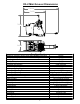
CG-2 Mini Groover Engine Assembly 13 11 7 12 ITEM NO. PART NUMBER DESCRIPTION QTY. 1 6075509 Engine Mount Weldment 1 2 2600580 Deutz Model D2011L03i 49 HP 1 3 2900084 1/2 SPLIT LOCK WASHER 4 4 2900192 1/2-13 x 2.25" Hex Head Cap Screw 2 5 2900058 1/2 FLAT WASHER 6 6 2903092 1/2-13 x 3.50" Hex Head Cap Screw 2 7 6075508 Exhaust Stabilizer Mount 1 8 2903164 M10-1.
CG-2 Mini Groover PTO Assembly 3 2 4 8 17 1 22 21 12 14 11 14 19 7 5 14 6 ITEM NO.
CG-2 Mini Groover Air Intake Assembly 13 12 14 11 2 3 10 4 5 6 9 8 16 13 1 ITEM NO. 1 2 3 4 5 6 7 8 9 10 11 12 13 14 15 16 17 18 17 PART NUMBER 6075401 2501385 2501384 2704336 2500423 3200117 2506684 6010052 3200847 3205561 2501388 2900138 2900031 2900567 2900329 2900126 2900341 2900024 18 16 7 15 Description Air Intake Bracket Mounting Band, Polymer Air Cleaner Complete Hose Elbow, 3" I.D. Restriction Indicator Close Nipple, 1/8" NPT Hose Elbow, 2-1/2" I.D. Connector Tube, 2-1/2" O.D. 2.
CG-2 Mini Groover Positraction Engagement Assembly 6 5 4 3 7 2 ITEM NO. PART NUMBER 1 6085101 2 3 4 5 6 7 8 9 2502135 2500007 2900665 2900239 6010095 2903018 2900013 2900018 1 8 7 9 40 Description Positraction Engagement Weldment Acme Threaded Rod, 3/4-6 x 11" Set Collar, 1/2" with Set Screw Belleville Washer, 1/2" Friction Washer, 1/2" Depth Stop Knob 3/8" Flat Washer 3/8-16 X 1.25" Hex Cap Screw Lock Nut, 3/8-16 Nylon QTY.
CG-2 Mini Groover Depth Stop Assembly 5 6 4 3 2 1 9 11 8 10 7 ITEM 1 2 3 4 5 6 7 8 9 10 11 PART NO. 6010097 2900665 2900058 2900239 6010095 2900132 2900158 2900084 2900037 2900007 2900004 QTY. 1 1 1 1 1 1 1 1 1 1 1 DESCRIPTION Depth Stop Weldment Belleville Washer, 1/2" Flat Washer, 1/2" SAE Friction Washer, 1/2" Depth Stop Knob Roll Pin, 3/16" x 1-1/4" Yoke, 1/2-13 Lock Washer, 1/2" Split Hex Nut, 1/2-13 Clevis Pin, 1/2" Dia.
CG-2 Mini Groover Hydraulic Pump Assembly 3 3 9 11 4 2 12 8 7 6 5 1 10 ITEM NO. 1 2 3 4 5 6 7 8 9 10 11 12 PART NUMBER 2600070 3200123 2700321 3200120 3200115 3200116 3200060 3200056 3200057 3200054 2900047 2900006 DESCRIPTION Hydraulic Pump Unit Pipe Nipple, 3/8" NPT x 2" Breather Cap Pipe Coupling, 3/8" NPT Elbow, 3/8" O-Ring to 1/4" F. Pipe Elbow, 1/4" O-Ring to 3/8" M. JIC Hex Nipple, 1/4" NPT Flow Control Valve, 1/4" NPT Elbow, 1/4" M. Pipe to 1/4" M.
CG-2 Mini Groover Battery Assembly 13 15 MAIN POWER SHUTOFF 6 3 4 11 12 14 16 5 BODY GROUND DETAIL A SCALE 2 : 4.5 ENGINE GROUND 2 STARTER POWER A 10 1 9 7 8 HYDRAULIC PUMP POWER ITEM NO.
CG-2 Mini Groover Fuel Tank & Supply Assembly 4 6 7 5 1 14 11 8 12 3 10 16 18 17 ITEM NO. 1 2 3 4 5 6 7 8 9 10 11 12 13 14 15 16 17 18 15 2 PART NUMBER 2501784 6010257 3200206 2504786 2500205 2501777 2501215 6010693 2501785 3200062 3200057 3200091 6010103 6013095 2900019 2900031 2900567 2900138 9 13 DESCRIPTION Fuel Tank Fuel Tank Mount Bar Pipe Plug, 1/4" NPT Fuel Tank Cap & Gauge Fuel Tank Grommet Fuel Valve w/Pick-Up Bushing, Rubber, Tank Fuel Supply Hose, 5/16" I.D.
CG-2 Mini Groover Water Supply Assembly 5 13 12 9 10 6 11 2 24 3 6 7 21 22 DETAIL B SCALE 1 : 6 7 25 B 23 1 8 14 15 16 DETAIL A SCALE 1 : 4 ITEM NO.
CG-2 Mini Groover Transmission Jackshaft Assembly 11 9 2 1 3 10 10 4 8 7 6 2 3 PART NUMBER 6010667 2501748 2501743 6010666 2900669 6010685 2900202 2900670 2500455A 6048229 2900617 11 3 9 3 3 ITEM NO. 1 2 3 4 5 6 7 8 9 10 11 2 2 6 5 Description Jackshaft Pivot Housing Retaining Ring, 42mm Internal Ball Bearing, 20mm x 42mm x 12mm Idler Jackshaft 20mm x 90mm (M16) Shoulder Bolt Bearing Spacer, 1/4" 5/8 SAE Flat Washer M16 Nylon-Insert Hex Locknut Pulley, 4" Single Groove Key, 3/16" Sq.
CG-2 Mini Groover Guide Wheel Assembly 9 8 8 9 3 7 4 1 ITEM NO. 1 2 3 4 5 6 7 8 9 PART NUMBER 6082000 2507007 6082001 2900031 2900567 2900138 2900141 2900295 2901406 2 5 6 47 Description QTY. Caster Plate Weldment 1 Rigid Caster 4" x 2" 1 Threaded Rod, 1"-8 x 8" 1 5/16 SPLIT LOCK WASHER 4 5/16" Flat Washer 4 5/16-18x1.00 HEX CAP SCREW 4 5/16-18 MEDIUM DUTY HEX NUT 4 1.
CG-2 Mini Groover Transmission Belt Tensioner Assembly 8 9 5 ITEM NO. 1 2 3 4 5 6 7 8 9 10 3 7 1 5 6 PART NUMBER 6075170 6010055 2903018 2900153 2900006 2900047 2500246 2500074 2900013 2504035 3 2 4 10 DESCRIPTION QTY. Belt Tension Arm 1 Friction Spacer 1 3/8" Flat Washer 2 Friction Washer, 3/8" 1 3/8 SPLIT LOCK WASHER 2 3/8-16 x 1.75 Hex Cap Screw 1 Shoulder Adapter, 3/8" Bore 1 Idler Pulley 3" 1 3/8-16 X 1.25" Hex Cap Screw 1 Spring, Ext.
CG-2 Mini Groover Front Pointer Assembly 6 4 3 10 9 5 8 7 4 1 9 12 ITEM NO. 1 2 3 4 5 6 7 8 9 10 11 12 2 11 PART NUMBER 6075413 6011152 6082003 2500740 2501409 2500007 2903096 2900127 2900026 2900025 2900013 2900105 49 Description Frame, Front Pointer Front Pointer Arm Front Pointer Rod Pointer Cap Wheel, 6" Set Collar, 1/2" with Set Screw 1/-13 x 5.50" Hex Head Cap Screw 1/2" USS Flat Washer 1/2-13 Nylon-Insert Hex Locknut 1/2-13 x 1.25" Hex Cap Screw 3/8-16 X 1.25" Hex Cap Screw 1/2-13 x 2.
CG-2 Mini Groover Parking Brake Assembly 14 ITEM PART NO. NUMBER 1 6011229 2 6011234 3 6011230 4 6011231 5 2501664 6 2900083 7 2903018 8 6011232 9 2900006 10 2900005 11 2900082 12 2900632 13 6011233 14 2500002 15 2900019 16 2900031 17 6048229 18 2900026 8 13 15 Description QTY. Bearing Housing Bar Friction Disc, 3/4" x 2-1/2" x 3/8" Pivot Pin Pivot Arm Ball Bearing, 3/4" x 1-5/8" x 7/16" Fender Washer, 1/4" x 1-1/4" 3/8" Flat Washer Brake Lever 3/8 SPLIT LOCK WASHER 3/8-16x1.
CG-2 Mini Groover Belt Location 1 2 ITEM NO. 1 2 3 PART NUMBER 2504025 2502668 2503416 3 Description Eaton Transmission Belt Belt, AP56 Banded Belt, 5/3V/600 - 5 Strand QTY. 1 1 2 *NOTE: IMAGE FOR ILLUSTRATION PURPOSES ONLY, NEVER OPERATE MACHINE WITHOUT ALL BLADE & BELT GUARDS IN PLACE.
Wiring Diagram ITEM 1 2 3 4 5 6 7 8 9 10 11 12 13 14 15 16 17 18 19 20 21 22 23 24 25 26 27 28 29 30 31 31 PART NO. 2801306 2800429 2800397 2800392 2800393 2800600 2800565 6079077 6079080 6079078 6079079 2600070 2700169 2800372 2800373 2801474 6010416 2800611 2800612 2800169 2800387 2800364 2703194 2703195 2800144 2801367 2702274 2701823 2800144 2800263 2800264 2800062 2800063 2800060 2800388 2800389 2703192 2700785 2700293 2800787 2700293 2800786 2700293 QTY.
EQUIPMENT AND PARTS WARRANTY Diamond Products warrants all equipment manufactured by it against defects in workmanship or materials for a period of one (1) year from the date of shipment to Customer.