
Manual


Wiring Diagram
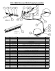
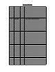
ITEM PART NO. QTY. DESCRIPTION
1 2801306 1 Control Panel Harness
2 2800429 1 Engine Harness
3 2800397 1 Tach Sensor Harness
4 2800392 1 Relay Harness
5 2800393 1 Hydraulic Pump Harness
6 2800600 1 Battery, 12V
7 2800565 1 Battery Disconnect Switch
8 6079077 1 Cable, Battery (POS) to Disconnect
9 6079080 1 Cable, Battery (NEG) to Ground
10 6079078 1 Cable, Disconnect to Lift Pump
11 6079079 1 Cable, Disconnect to Starter
12 2600070 1 Hydraulic Pump Unit
13 2700169 1 Solenoid, Motor
14 2800372 1 Pushbutton Switch, Raise
15 2800373 1 Pushbutton Switch, Lower
16 2801474 2 Switch, N.O. Pushbutton
17 6010416 1 Tach/Hour Meter (VDO) Calibrated
2800611 2 (Light Socket)
2800612 2 (Light Bulb, Wedge Base)
18 2800169 1 Magnetic Sensor
19 2800387 1 Circuit Breaker, 25A
2800364 1 Circuit Breaker Boot, Red
20 2703194 1 Ignition Switch & Key
2703195 1 (Ignition Key Only)
21 2800144 1 Relay, Ignition
22 2801367 1 Emergency Stop Button
23 2702274 1 Starting Motor (Includes #24)
24 2701823 1 Solenoid Switch
25 2800144 1 Relay, Water Safety Switch
2800263 1 Relay Connector
2800264 4 Wire Terminal, 1/4" Push-on
26 2800062 1 Toggle Switch
2800063 1 Boot, Toggle Switch
27 2800060 1 Water Pressure Safety Switch
28 2800388 1 Fuse Panel, 6 Circuit
2800389 2 Fuse, 10A Red ATO/ATC
29 2703192 1 Temperature Gauge, Pricol
30 2700785 1 Alternator Light
2700293 1 (Bulb Only)
31 2800787 1 Oil Temperature Light
2700293 1 (Bulb Only)
31 2800786 1 Oil Pressure Light
2700293 1 (Bulb Only)